2 contact sensors – Controlled Products Systems Group 9050-080 User Manual
Page 27
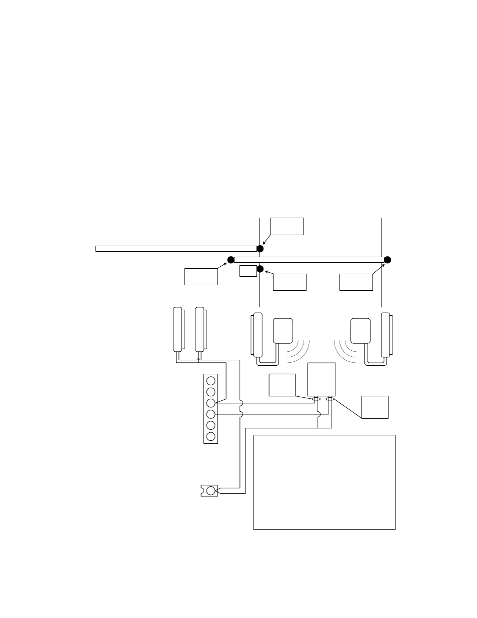
2.3.2 CONTACT
SENSORS
• Disconnect power to the gate operator before installing the contact sensors.
• Connect the contact sensors as shown below to the auxiliary terminal strip. Note that all
commons connect to main terminal 12.
• Contact sensors must be located at the leading edge, trailing edge, and post mounted both
inside and outside of the vehicular sliding gate. Additional contact sensors may be added for
additional protection where an entrapment zone may exist.
• Hardwired contact sensors must be located and wiring arranged so that the communication
between the sensor and the gate operator is not subjected to mechanical damage.
• Inputs from sensing edges/receiver to circuit board are NORMALLY OPEN.
• Diagram does not show power wiring to RF receiver.
Roadway
Fence
Gate
Open Photo-Beam
Close Photo- Beam
Open Edge
Close Edge
Alarm Reset
Alarm Signal
Auxiliary
Terminal Strip
Contact Sensor Wiring Diagram
Notes:
Inputs from sensing edges/receiver to circuit
board are Normally Open (N.O.).
Diagram does not show power wiring to RF
receiver.
If using contact sensors as the secondary
entrapment protection device, the UL Standard
specifies that one or more sensors be located at
the leading edge, trailing edge, and post mounted
both inside and outside of a vehicular horizontal
slide gate.
Trailing
Edge
Leading
Edge
Inside
Post Mount
Outside
Post Mount
Lead
Edge
TX
Trail
Edge
TX
Tra
il Ed
ge
Le
ad
Ed
g
e
2 CH
Rec'vr
In
si
d
e
P
o
s
t
Outs
ide
P
o
st
Trailing
edge
relay
Leading
edge
relay
Main Terminal 12
Common
Figure 27
17