1 non-contact sensors, 3 secondary entrapment protection device wiring – Controlled Products Systems Group 9050-080 User Manual
Page 26
2.3 SECONDARY ENTRAPMENT PROTECTION DEVICE WIRING
Secondary entrapment protection devices must be installed to insure a safe operating environment
and to reduce the risk of entrapment. This operator has inputs for non-contact sensors and contact
sensors for both opening and closing gate cycles. Secondary entrapment protection may be provided
by a combination of both type sensors. See Section 5.3 for a list of acceptable secondary entrapment
protection devices.
2.3.1 NON-CONTACT
SENSORS
• Disconnect power to the gate operator before installing the non-contact sensors.
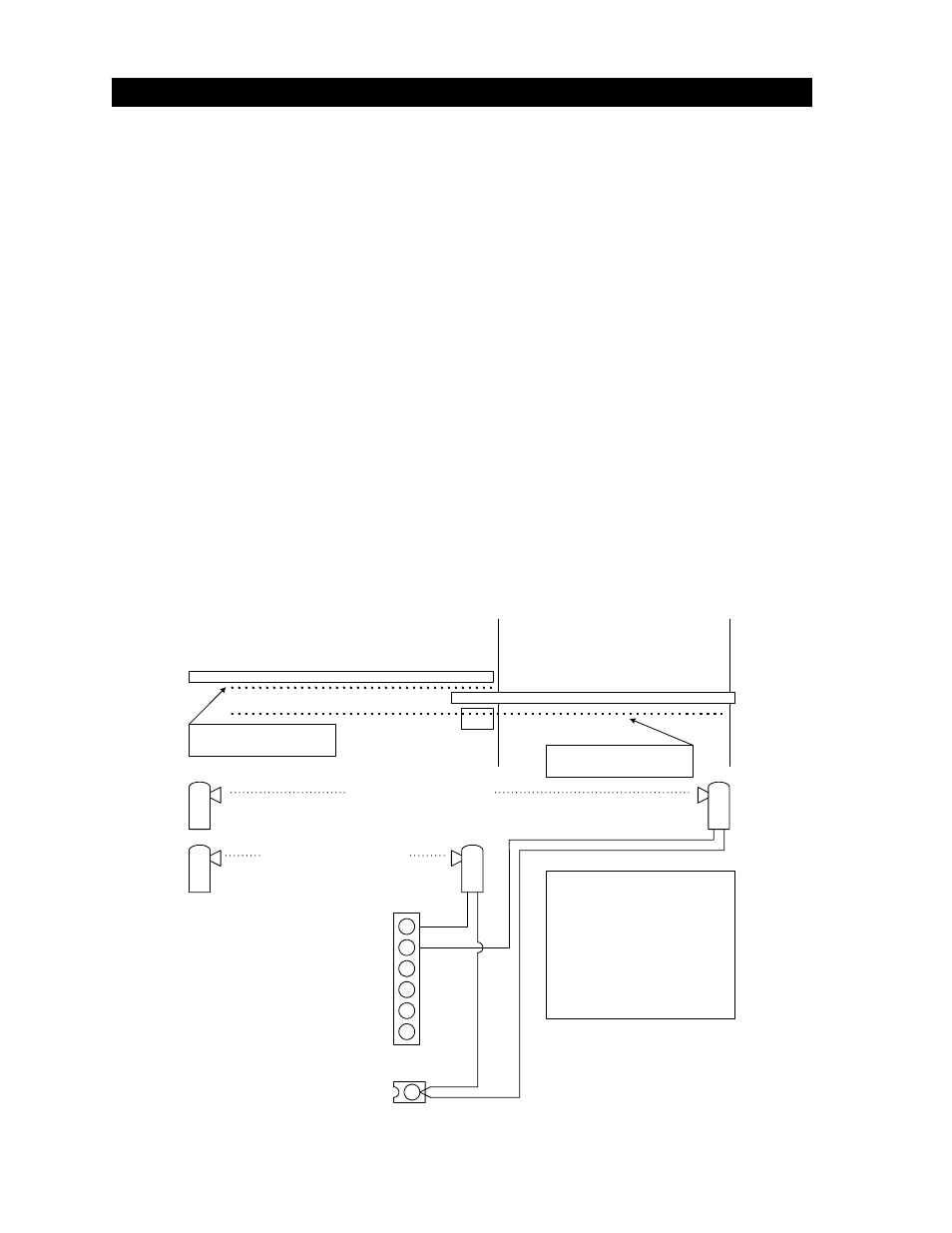
• See figure 26 for suggested placement of sensors. (Diagram is for illustration purposes only.
Actual placement of the sensors is dependent on the installation requirements). One or more
non-contact sensors shall be located where the risk of entrapment or obstruction exists, such
as the perimeter reachable by a moving gate or barrier.
• Use only UL listed (or equivalent) non-contact sensors.
• Connect the non-contact sensors as shown below to the auxiliary terminal strip. Note that all
commons connect to main terminal 12. Inputs from photo-beam to circuit board are
NORMALLY OPEN.
• Diagram does not show power wiring to photo-beams.
• Open photo-beam must be placed so that it covers that portion of the fence that the gate
covers when it is fully open.
Roadway
Fence
Gate
Open direction
non-contact sensor
Close direction
non-contact sensor
Open Photo-Beam
Close Photo- Beam
Open Edge
Close Edge
Alarm Reset
Alarm Signal
Au
xili
ary
T
e
rm
inal
St
ri
p
Non-Contact Sensor Wiring Diagram
Notes:
Inputs from photo-beam to circuit
board are Normally Open (N.O.).
Diagram does not show power
wiring to photo-beams.
Open photo-beam must be placed
so that it covers that portion of the
fence that the gate covers when it
is fully open.
Close Direction Protection
Open Direction Protection
Main Terminal 12
Common
Figure 26
16