1 pad mounted operators, 2 post mounted operators, 4 operator installation – Controlled Products Systems Group 9050-080 User Manual
Page 16
1.4 OPERATOR
INSTALLATION
Prior to mounting the gate operator, be sure that the chain knockouts and chain idlers are set for the
mounting position (front, center or rear) and the mounting option chosen (pad or post). Refer back to
SECTION 1.2.
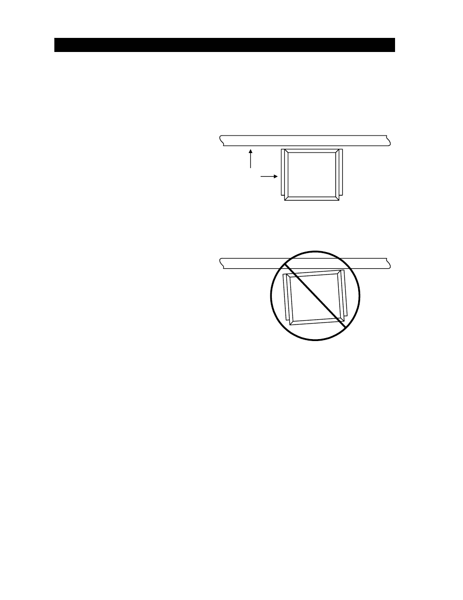
1.4.1 PAD
MOUNTED
OPERATORS
• Position the operator on the pad
so that there is a minimum
clearance of one (1) inch between
the back of the operator housing
and the gate.
90°
• IMPORTANT!! Be sure that the
operator is parallel to the gate!
Installing the operator in any other
manner will cause excessive
chain noise, chain wear and
stretching, and premature idler
failure.
• Mark the mounting holes on the
mounting pad. Use a concrete
drill bit to drill the mounting holes
to the size and depth required for
the anchors being used. We
recommend minimum 3/8 x 2
sleeve anchors (not supplied).
• After drilling the mounting holes,
clean them out and install the
sleeve anchors. Position the
operator over the anchors and
tighten.
Figure 9
1.4.2 POST
MOUNTED
OPERATORS
• Position the operator on the mounting plate so that the mounting holes are in alignment. If
the mounting plate/post assembly has been installed correctly, there should be a minimum of
one (1) inch clearance between the back of the operator housing and the gate, and the
operator should be parallel to the gate. If these conditions do not exist, make corrections
now!
• IMPORTANT!! Be sure that the operator is parallel to the gate! Installing the operator in any
other manner will cause excessive chain noise, chain wear and stretching, and premature
idler failure.
• Secure the operator to the mounting plate/post assembly using six (6) ½-13 x 1 ½ bolts, lock
washers and nuts (or equivalent hardware). NOTE: Hardware is not supplied with the
operator or mounting plate.
6