3 rear position pad or post mount, 4 center position post mount – Controlled Products Systems Group 9050-080 User Manual
Page 13
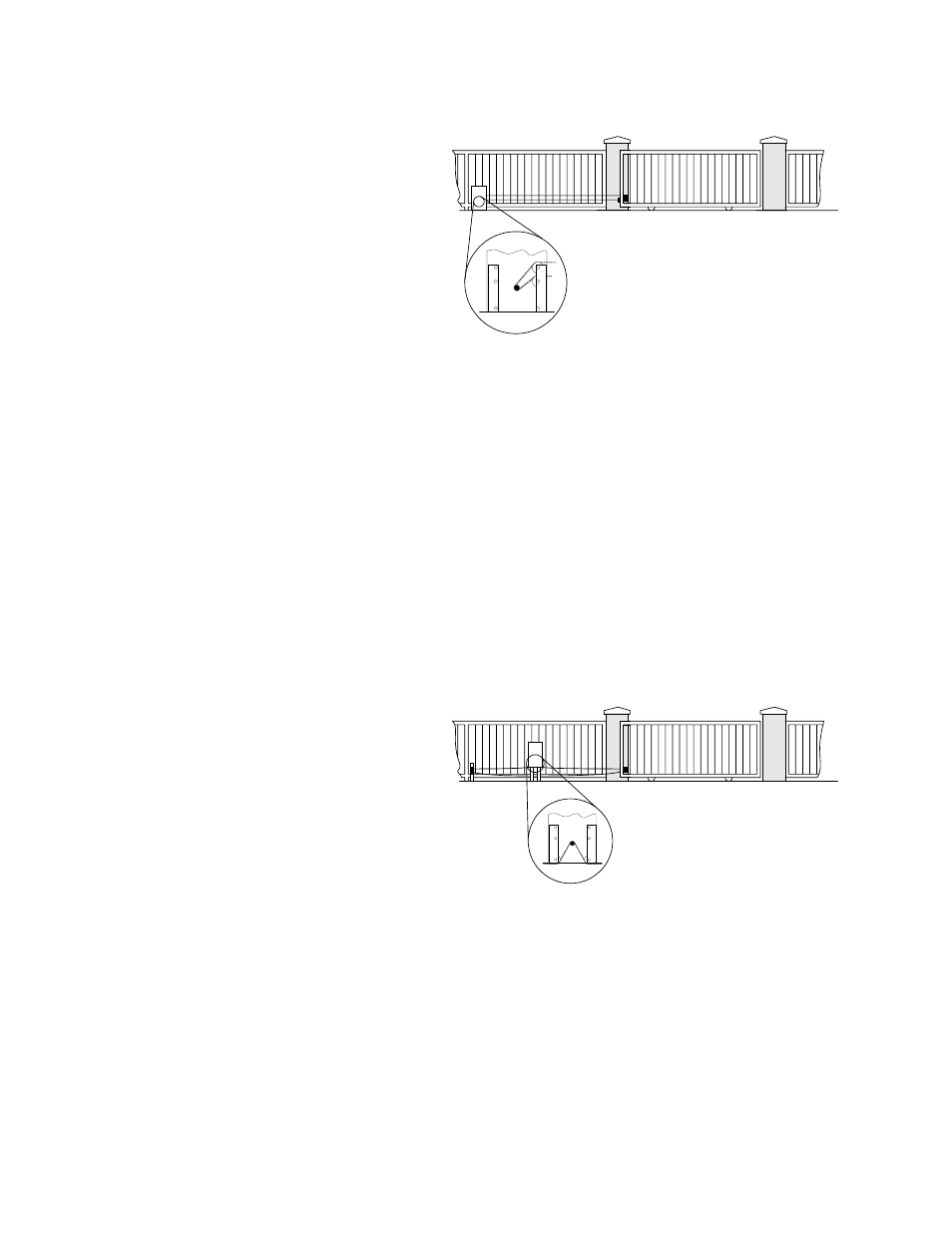
1.2.3 REAR POSITION PAD OR POST MOUNT
• Set one chain idler at the top
position and one chain idler at
the center position on the same
side of the operator.
• Remove the top and bottom
chain knockouts from the side of
the operator.
• Chain enters and exits the
operator from the same side.
Chain is attached to one end of
the gate.
• This mounting method hides the
chain when looking at the gate
from the front.
• ADDITIONAL HARDWARE REQUIRED: Endless Idler Assembly P/N 2600-818. Additional
length of #41 Chain P/N 2600-441 (20 ft.). Note: additional chain may be required depending
on the length of the gate.
• If operator is post mounted: Post Mount Base Plate P/N 2600-418 and two (2) 4” x 4” steel
mounting post at least three feet in length. Mounting post are not available from DoorKing.
1.2.4 CENTER POSITION POST MOUNT
• Set both chain idlers in the bottom
position.
• DO NOT remove chain knockouts.
Using this mounting method, the
chain enters and exits the
operator from the bottom.
• Chain passes through the
operator and is attached to one
end of the gate.
Figure 4
• This mounting method allows for
the use of chain support
attached to the gate. This is useful with long gates and helps prevent chain “stretching.”
Figure 5
• ADDITIONAL HARDWARE REQUIRED: Two (2) Endless Idler Assemblies P/N 2600-818.
Additional length of #41 Chain P/N 2600-441 (20 ft.). Note: additional chain may be required
depending on the length of the gate. Post Mount Base Plate P/N 2600-418 and two (2) 4” x
4” steel mounting post at least three feet in length. Mounting post are not available from
DoorKing.
3