Installation, Technical specifications – Controlled Products Systems Group 104301 User Manual
Page 7
7
FAAC Model S418 Swing Gate Operator
3. INSTALLATION
Technical Specifications
S418
Power Supply (VDC)
24
Nominal Power (W)
35
Absorbed Current (A)
1.5
Maximum Thrust Force (lbf)
405
Stroke (inches)
13 3/4 1
Cycles per day at 68 °F (approx)
80
Class of operation
Residential
Rod speed (inches/sec)
0.7
Maximum Size of Leaf (feet)
12
Ambient Operating Temperature (°F)
-4 to 131
Operator Weight (lbs)
13.2
Protection Class
IP54
1 If you do not use the mechanical stops on opening and
closing, the operator stroke increases to 15 1/4 inches.
2.
TECHNICAL SPECIFICATIONS
3.2
PRELIMINARY CHECKS
The structure of the gate directly influences the reliability
and safety of the automated system. To ensure correct
operation, the structure of the existing gate, or that to be
fitted, must have the following characteristics:
• The length of leaf must conform to what is shown in the
technical characteristics of the operator (Section 2).
• The structure of the leaves must be sturdy and rigid,
suitable for an automated system.
• There must be regular and uniform movement of the
leaves, with no friction or sticking along their entire
movement.
• Hinges must be suitably sturdy and in good condition.
It is recommended that any metalwork operations
should be performed prior to installing the automated
system.
3.1
ELECTRICAL SETUP
When laying electrical cables, use conduits with adequate
rigidity and/or flexibility.
To avoid any type of interference, always separate low-
voltage accessories and command connection wiring from
power supply cables, use separate sheaths.
Fig. 3
Part
Description
Cables
1
Operators
2 x AWG 14 (max 30’)
AWG 12 (max 50’)
AWG 10 (max 100’)
2
Control Unit
3 x AWG 14 (AC Power)
3
TX Photocells
4 x AWG 20
4
RX Photocells
2 x AWG 20
5
Key Selector
2 x AWG 20 (1 contact)
6
Flashing Lamp
2 x AWG 14
7
External Antenna
Coaxial Cable
8
Mechanical Stops
Dimensions in Inches
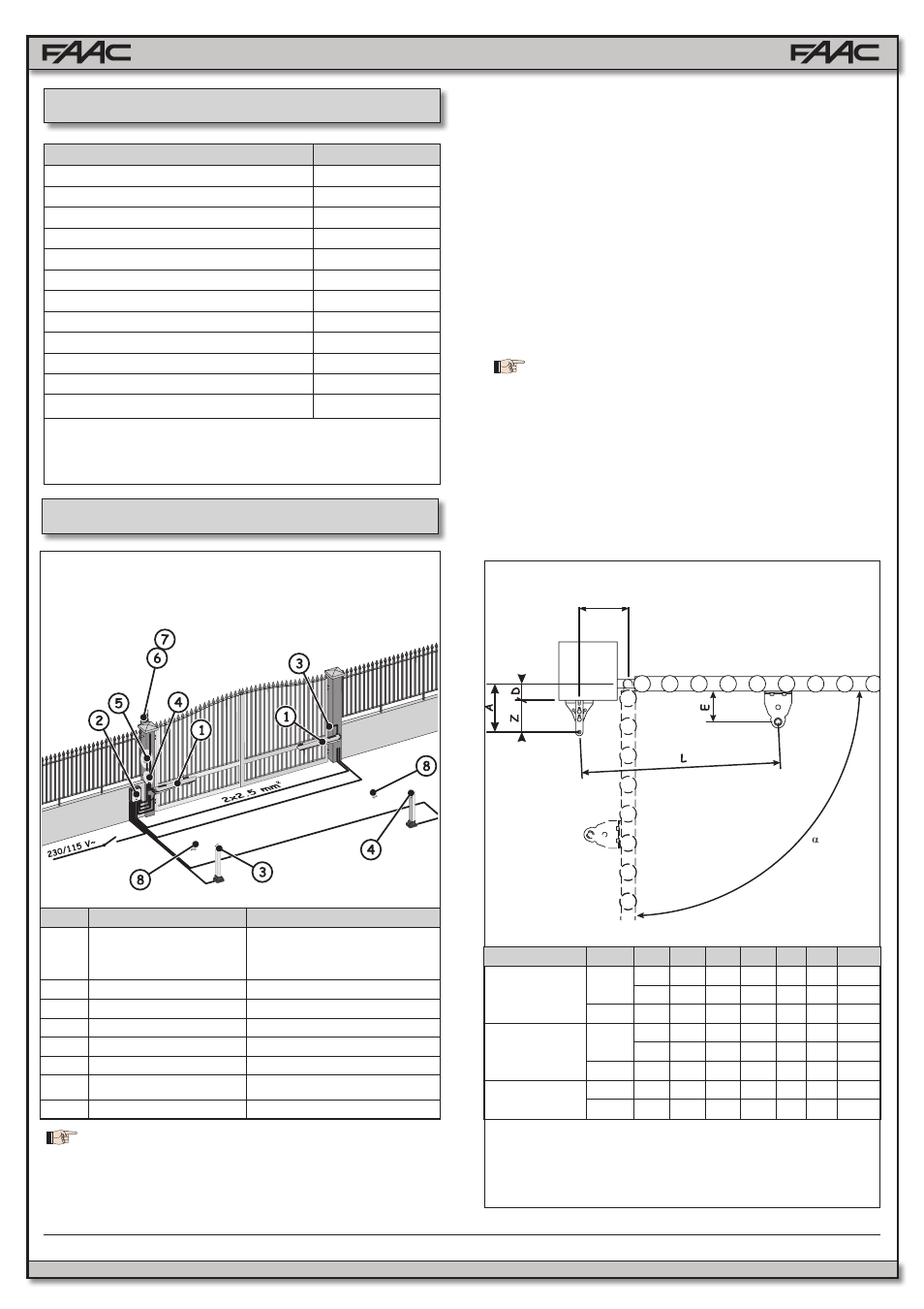
3.3
INSTALLATION DIMENSIONS
Determine the assembly position of the operator, referring to
Figure 4 and relative table. It is a good idea at this stage to
choose whether or not you want to use the built in mechanical
positive stops; eliminating the mechanical stops increases the
working stroke of the operator and values
A and B must be
changed.
Fig. 4
a
A
B C 1 D 2 Z 3 L
E 3
With both
stops
90°
6½ 6½ 13 3½
3 27
4⅛
6⅞ 6⅞ 13¾ 3½ 3⅛ 27
4⅛
110°
6
6 13⅜ 3⅛ 2¾ 27
4⅛
With open
stop
90°
6⅞ 6½ 13⅜ 4
3 28
4⅛
7
7 14⅛ 4
3⅛ 28
4⅛
110° 6¼ 6¼ 14⅛ 3½ 2¾ 28
4⅛
With no stops
90°
7
7 14⅛ 4
2¾ 28
4⅛
110° 6⅝ 6⅝ 15
4
2¾ 28
4⅛
1 Working stroke of the operator.
2 Maximum value.
3 Minimum value.