Controlled Products Systems Group 104301 User Manual
Page 17
FSW
STP CL OP
FSW
STP CL OP
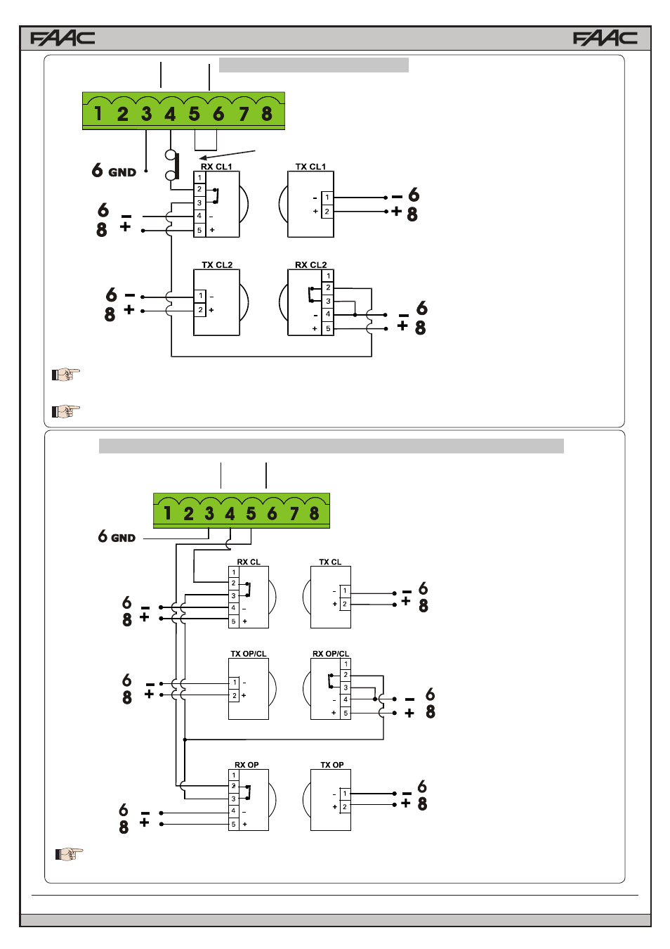
Connection of two pairs of closing photocells
Connection of a pair of closing photocells, a pair of opening photcells and a pair of opening/closing photocells
Other optional safety devices to connect in series
Fig. A7
Fig. A8
To use the FAIL-SAFE mode connect the negative power supply of the transmitters to OUT (pin 9), and
set dip-switch 11 and 12 to ON on DS1
When using the FAIL-SAFE mode also the safety inputs not used (FSW CL , FSW OP) must be connected
to OUT (pin No. 9)
To use the FAIL-SAFE mode connect the negative power supply of the transmitters to OUT (pin 9),
and set dip-switch 11 and 12 to ON on DS1
RX= Photocell Receiver
TX= Ptotocell Transmitter
CL= Closing
OP= Opening
RX= Photocell Receiver
TX= Ptotocell Transmitter
CL= Closing
OP= Opening
A5
E024U CONTROL BOARD
- GNC-1 (1 page)
- -108712 (33 pages)
- 1044372 (28 pages)
- 1042071277 (28 pages)
- 104207177 (28 pages)
- 10441811 (29 pages)
- 1044182 (28 pages)
- 1044682 (28 pages)
- 104471 (28 pages)
- 104572 (24 pages)
- 104572 (27 pages)
- 10468583 (36 pages)
- 1049062 (17 pages)
- 106753 (28 pages)
- 108758 (40 pages)
- 109773 (19 pages)
- 10978021 (6 pages)
- 109902 (27 pages)
- 1150-080 (30 pages)
- 1600 (17 pages)
- 1650ETL (23 pages)
- 1650ETL-1K (32 pages)
- 1601-081 (36 pages)
- 1602-091 (42 pages)
- 1602-091 (42 pages)
- 1603-166 (38 pages)
- 1603-166 (42 pages)
- 1603-166 (40 pages)
- 444 XS ST (98 pages)
- 222X383 (84 pages)
- 3020HX (24 pages)
- 3600ETL-1K (36 pages)
- 4500SW (32 pages)
- 6004-080 (34 pages)
- 6002-080 (32 pages)
- 6003-080 (22 pages)
- 6100-083 (2 pages)
- 6100-083 (46 pages)
- 6100-083 (56 pages)
- 6300-087 (52 pages)
- 6300-087 (59 pages)
- 6400-080 (28 pages)
- 6500-087 (48 pages)
- 6500-087 (46 pages)