Manual operation – Controlled Products Systems Group -108710 User Manual
Page 12
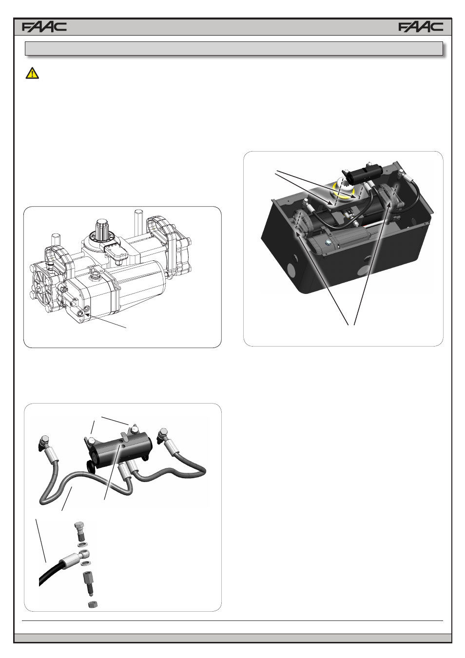
Fastening bolts for the release system
Bleed screws
Fig. 18
Banjo Bolt
Hydraulic Hose
Union bolt
1
Fig. 19
4.2.1 INSTALLATION PROCEDURE
The installation of the hydraulic release could have let air in the
circuit, causing irregular operation like an incorrect movement
of the leaf and excessive noise during operation.
To solve this problem, operate as follows:
1) Command an opening movement of the gate.
2) During the leaf movement, loosen the opening bleed screw
(Fig.20 ref.1 )
3) Let air come out from the hydraulic circuit through the bleed
screw until non-emulsified oil comes out.
4) Tighten the bleed screw before the operator ends the opening
cycle.
5) Command a closing movement of the gate.
6) During the leaf movement, loosen the closing bleed screw
(Fig.20 ref. 2)
7) Let air come out from the hydraulic circuit through the bleed
screw until non-emulsified oil comes out.
8) Tighten the bleed screw before the operator ends the closing
cycle.
9) Repeat the operations, if necessary.
10) Restore the oil level until it is just under the cap, using the
oil supplied (Fig. 21 ref.1).
2
4.2.2 BLEEDING PROCEDURE
The S800H operator kit comes with a field installable hydraulic
manual release, that can be conveniently mounted on top of
the load bearing box
1) Release the operator using the built in hydraulic release
2) Fasten the external release body to the load bearing box
system using the two supplied M8 screws (fig. 19 ref. 1)
3) Remove the bleed unions on the operator, then connect
those supplied with the release system (Fig. 19 ref. 2
3) Re-lock the built in manual release.
If the gate has to be moved manually due to a power cut or
fault of the automated system, you can use the hydraulic
release device with the release key (Fig.17):
1) Remove the cover from the bearing case.
2) Turn the release screw
- To RELEASE, turn the screw counter-clockwise by one turn.
(DO NOT COMPLETELY UNFASTEN THE SCREW TO AVOID
SPILLING THE OIL.
- To re-engage the hydraulic operation, turn the screw
clockwise up to the mechanical stop point. (DO NOT
OVERTIGHTEN)
RELEASE SCREW
Fig.17
4.1 BUILT IN HYDRAULIC RELEASE
MAKE SURE TO CUT POWER BEFORE RELEAS-
ING OR LOCKING THE OPERATOR
4. MANUAL OPERATION
4.2 EXTERNAL HYDRAULIC RELEASE
12
FAAC Model S800H Swing Gate Operator