Ab c – Controlled Products Systems Group -108710 User Manual
Page 10
A
B
C
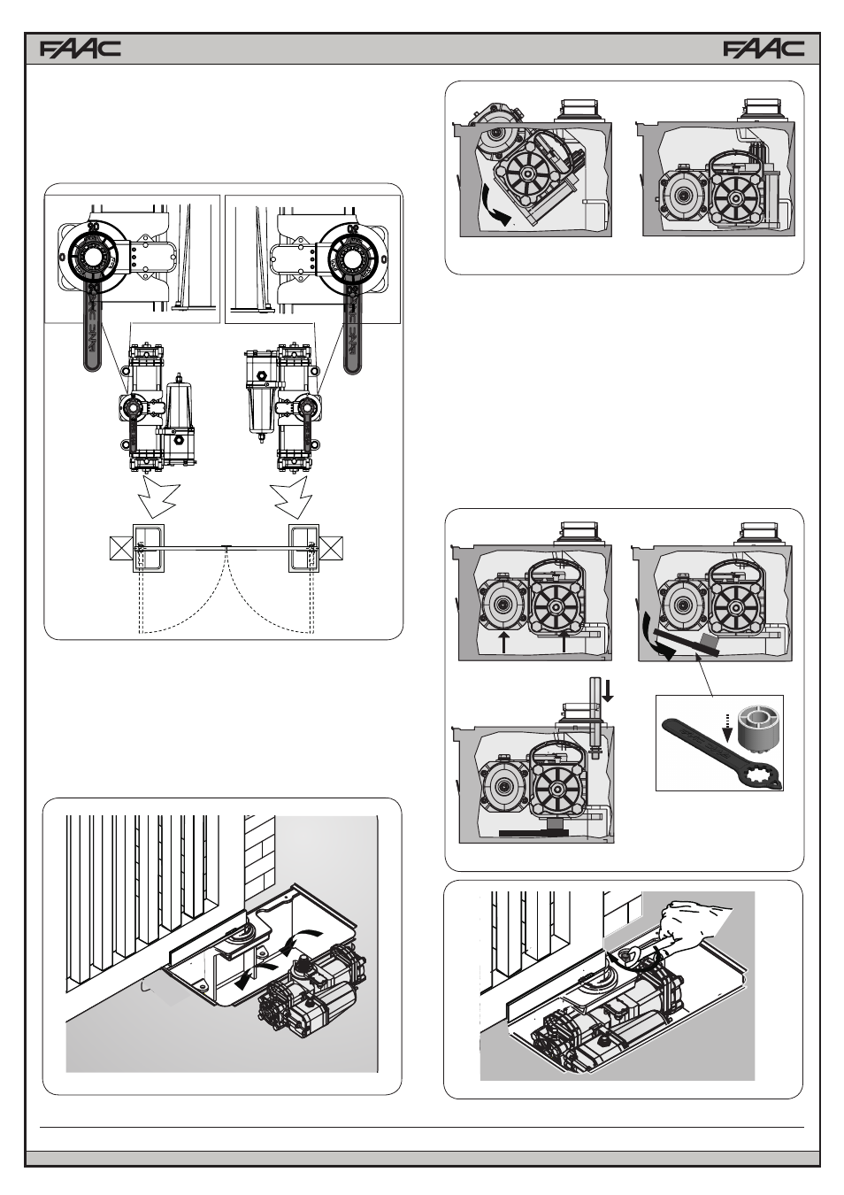
8) Grease the pinion and insert the operator in the load bearing
box as shown in Fig.8-9,
9) Raise the operator with its handles (Fig.10 ref. A), inserting the
pinion in the grooved bushing of the bearing case. To facilitate the
operation, slightly rotate the operator until coupling takes place.
Fig.7
Fig.9
Fig.10
Fig.11
10) Place the supplied plastic wrench with the spacer under the
operator, as shown in figure 10 ref. B, C
12) Insert and screw in the fastening screws with the supplied
lockwasher as shown in Fig. 10 ref. C, in order to secure the
operator to the load bearing box as shown in Fig. 11.
13) Close the gate and check if the closing travel-limit stop is
correctly positioned; if necessary, adjust the travel-limit stop,
referring to the instructions in paragraph 3.4.
14) Open the gate and check if the opening travel-limit stop is
correctly positioned; if necessary, adjust the travel-limit stop,
referring to the instructions in paragraph 3.4.
15) Hydraulically re-lock the operator as per instructions in
chapter 4
NOTE: if necessary, lightly tighten the closing travel-limit screw
7) Turn the operator pinion with the supplied wrench until the mark
point to 90° and then remove the wrench (see Fig. 7)
Fig.8
10
FAAC Model S800H Swing Gate Operator