Controlled Products Systems Group 1042001 User Manual
Page 8
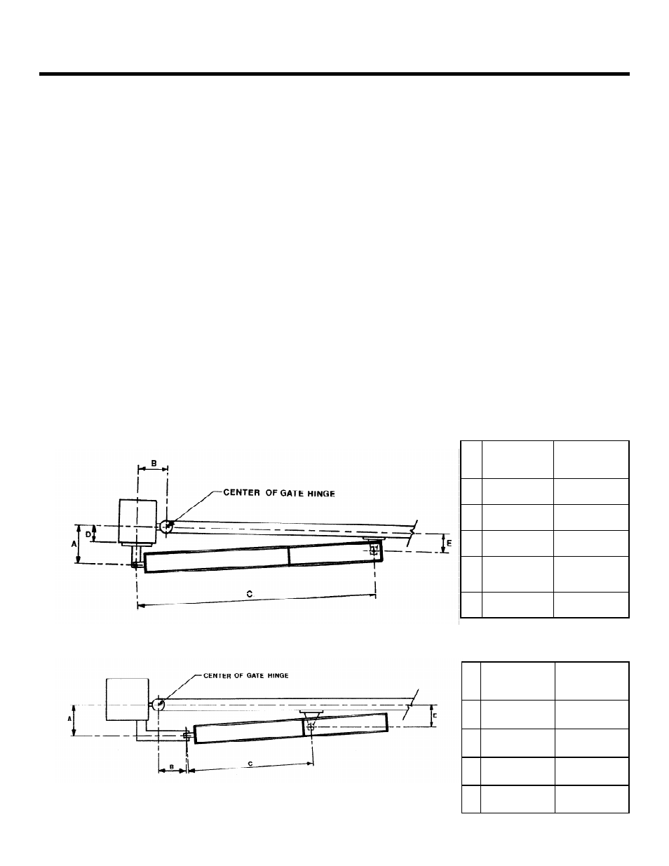
Figure 4. An inward swinging gate, top view: important mounting dimensions
Figure 5. An outward swinging gate, top view: important mounting dimensions
422
Standard
A
4-3/4 in.
( 12 cm)
B
4-3/4 in.
(12 mm)
C
27 in. (673
mm)
E
Must be
less than A
422
VHS
3-1/8 in.
(8 cm)
3-1/8 in.
(8 cm)
23-1/4 in.
(59 cm)
Must be
less than A
422
Standard
A
4-3/4 in.
(114 mm)
B
4-3/4 in.
(114 mm)
C
36-5/8 in.
(93 cm)
D
Max
2-3/4 in.
(7 cm)
E
Must be
less than A
422
VHS
3-1/8 in.
(8 cm)
3-1/8 in.
(8 cm)
29-3/4 in.
(75.5 cm)
Max
1-1/8 in.
(2.9 cm)
Must be less
than A
Page 8
December, 2003
422 Operator And
455 D Control Panel Installation Manual
Hold the front mounting bracket flush against the gate.
Mark the location of the front mounting bracket.
Remove the operator from the gate. Remove the front
mounting bracket from the swivel joint.
Note:
Clamping the front mounting bracket at the
marked location before checking the swing, as
instructed below, will ensure proper location of the
front mounting bracket.
Bolt or weld the front mounting bracket to the marked
location on the gate.
WARNING!
Do no weld the front mounting
bracket with the operator attached. Doing so will
seriously damage the operator.
A
TTACH
THE
O
PERATOR
TO
THE
G
ATE
Re-attach the operator to the mounting brackets. Once
the operator is mounted and level, remove the vent
screw from the bottom of the rear flange. (See Figure 1)
Use the 3mm hex key on the end of the screwdriver
provided.
WARNING!
Failure to remove the vent screw
may result in erratic operation of the operator or
blown
seals.
Slowly move the gate open and close.
WARNING!
The piston should not bottom out in
either direction. Doing so will seriously damage
the
operator.
Be sure that the gate reaches the positive stop before the
piston bottoms out. Adjust the swivel joint if necessary.
After checking the swing of the gate, secure all nuts and
bolts, including the jam nut on the swivel joint.
Once the operator is secure, install the protective cover
over the piston of the operator, first insert the two spacers
(items labeled 2 in Figure 6) in the front flange of the
operator as shown. The spacers dampen any vibrations to
the operator.
Once the protective cover is installed, swing the gate to
ensure that it does not contact the cover at any point of
the swing.
Re-engage the operator by inserting the key in the locking
cap (see Figure 3) and turning it clockwise until snug.
Remove the key.