455 d c, Ont r o l, Ane l – Controlled Products Systems Group 1042001 User Manual
Page 21: Nsta lla ti o n, Ns tru c tio n s, Advanced programming
Page 21
December, 2003
422 Operator And
455 D Control Panel Installation Manual
T
HE
455 D
C
ONT
R
O
L
P
ANE
L
I
N
STA
LLA
TI
O
N
I
NS
TRU
C
TIO
N
S
ADVANCED PROGRAMMING
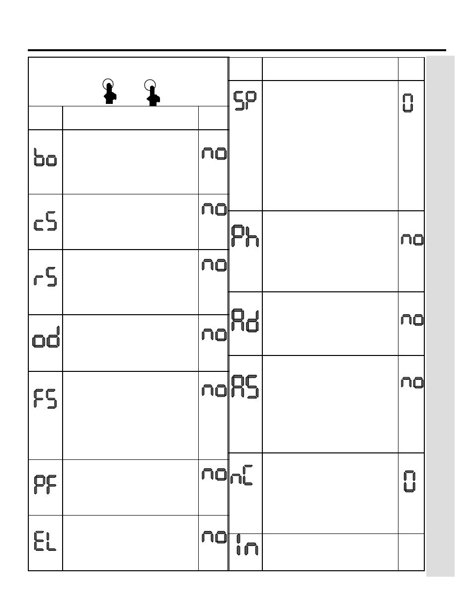
+
Display Function
De-
fault
M
AXIMUM
T
ORQUE
AT
I
NITIAL
T
HRUST
:
The motors operate at
maximum torque (ignoring the
torque setting) at start of movement.
Useful for heavy leaves.
4 = Enable
No = Disabled
L
AST
S
TROKE
AT
C
LOSING
:
The motors are activated at full
speed for 1s to facilitate locking of
the electric lock.
4 = Enable
No = Disabled
R
EVERSING
S
TROKE
:
Before opening, while the gate is
closed, the motors thrust to close
for 2 s thus facilitating release of the
electric lock.
4 = Enable
No = Disabled
L
EAF
2 O
PENING
D
ELAY
(2
S
):
Enables delayed start (at opening) of
leaf 2, avoiding interference between
leaves.
4 = Enable
No = Disabled
F
AIL
S
AFE
:
If this function is activated, it en-
ables a function test of the photo-
cells before any gate movement. If
the test fails (photocells not service-
able), the gate does not start the
movement.
4 = Enable
No = Disabled
P
RE
F
LASHING
(5
S
):
Activates the flashing lamp for 5s
before start of movement.
4 = Enable
No = Disabled
E
LECTRIC
L
OCK
ON
L
EAF
2:
For using the electric lock on leaf 2
instead of on leaf 1.
4 = Enable
No = Disabled
F
+
Display Function De-
fault
I
NDICATOR
-L
ICHT
:
If 0 is selected, the output functions
as a standard indicator-light (lighted
at opening and pause, flashing at
closing, and off when gate closed).
Different figures correspond to timed
activation of the output, which can be
used (via a relay) to power a courtesy
lamp. Time can be adjusted from 0
to 59s in 1s increments, and from 1.0
to 4.1 min. in 10s steps.
0 = Standard Indicator-Light
From 1 to 4.1 = Timed Output
C
LOSING
P
HOTOCELLS
REVERSE
AT
RELEASE
:
Enable this function if you
want the closing photocells to stop
the gate movement and reverse it
after the beam is cleared. Default set-
ting is immediate reverse.
4 = Enable
No = Disabled
A.D.M.A.P. F
UNCTION
:
If this function is enabled, the safety
devices operate in compliance with
French standard NFP 25/362.
4 = Enable
No = Disabled
A
SSISTANCE
R
EQUEST
(
COMBINED
WITH
NEXT
FUNCTION
):
If activated,
at the end of countdown (settable
with the next function, i.e. “Cycle pro-
gramming”) it effects 8s of pre-
flashing at every Open pulse (job re-
quest). Can be useful for setting
scheduled maintenance jobs.
4 = Enable
No = Disabled
C
YCLE
P
ROGRAMMING
:
For setting count down of system
operation cycles. Settable (in thou-
sands) from 0 to 99 thousand cycles.
The displayed value is updated as
cycles proceed. This function can be
used to check use of the board or to
exploit the “Assistance Request” func-
tion
.
E
XIT
P
ROGRAMMING
:
Exit from programming and return to
display of inputs status.