CNB ID2810PVF User Manual
Page 9
XNET Network Dome Camera User’s Guide
y 100BaseT (RJ45)
100Mbps Ethernet connector (RJ-45) with proprietary PoE.
-
Link LED: Continuous yellow light means that network cable is plugged in. It will
flicker when there is traffic.
-
Status LED: Green color indicates that the camera is in normal operation mode,
while RED color indicates that the camera is in abnormal condition.
y DC
Power
Power input of XNET. DC 12V
camera when power is supplied through a LAN cable using proprietary PoE.
This will damage the camera!
caused by applying power using both connectors.
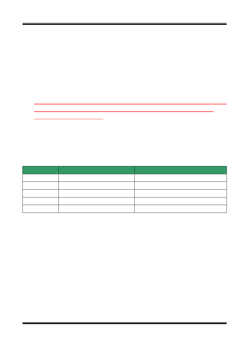
y Sensor In/Relay Out
Used for connecting sensor, and alarm devices to XNET. Note that the each signal is
differentiated by color of cable.
Cable color
Description
Misc.
Red
Sensor In (+)
NC/NO selectable in admin mode.
Black
Sensor In (-)
NC/NO selectable in admin mode.
Orange
Relay out
Normal close
Brown Relay
out
Common
Yellow
Relay out
Normal open
Sensor Input : Connect external alarm sensors such as the infrared sensors, heat
sensor, magnetic sensors, etc. NC/NO selectable in the admin page.
Relay Output : It is used for connecting external alarm generators such as sirens,
flashing light, etc. When activated, relay output configures a closed circuit.
Please refer to Section 6.1 for more detailed description on the Sensor In and
Relay Out connections.
9 of 44