Tips for using xnet, Sensor-in and relay-out – CNB ID2810PVF User Manual
Page 38
XNET Network Dome Camera User’s Guide
6. Tips for Using XNET
6.1. Sensor-IN and Relay-OUT
Use the Sensor-In and Relay-Out Cable to connect various sensing and alerting devices.
Examples of sensing devices are infrared sensors, motion sensors, heat/smoke sensors,
magnetic contact sensors, etc. Use the *Relay-Out connector for connecting device such as
loud speakers, flashing lights, or access control devices. * Make sure to follow the
recommended current limitations for this relay (AC/DC 30V @ 1 amp). An auxiliary relay may
be needed.
Cable color
Description
Misc.
Red
Sensor In (-)
NC/NO selectable in admin mode.
Black
Sensor In (+)
NC/NO selectable in admin mode.
Orange
Relay out
Normal close
Brown Relay
out
Common
Yellow
Relay out
Normal open
Figure 6-1. ALARM-IN/ALARM-OUT Cable
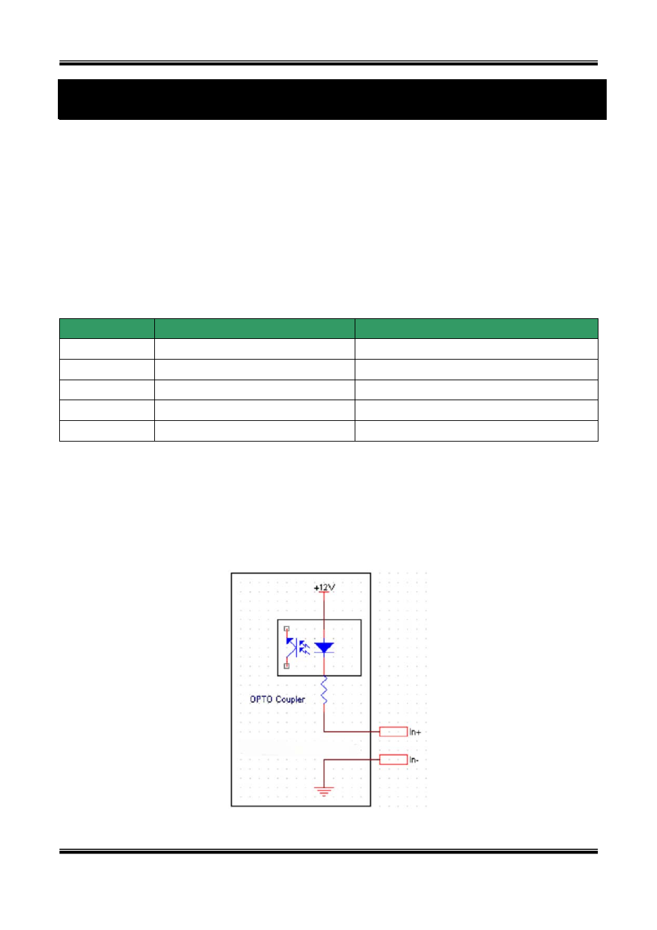
6.1.1. ALARM-IN
Connect the two wires of the sensors to “Alarm In”. The sensor type can be set in Administrative
mode. Output lines providing on-off switching are connected between “+“ and “-” pins. Figure
6-2 shows the input circuit of “Alarm In”.
Figure 6-2. ALARM-IN circuit
38 of 44