2 summing, Umming – Cleveland Motion Controls ULTRA ISC SERIES SLIM CELL TRANSDUCER REV AA User Manual
Page 22
U
LTRA
ISC
S
ERIES
S
LIM
C
ELL
T
RANSDUCER
MAN-70434-0
R
EV
AA
3.2 S
UMMING
In the majority of applications, loadcells are used in pairs. The net tension of the web must
therefore be represented by the summation of the two loadcell signals. As described above, the
summation can be done in software, so long as both analog channels can be independently
observed. When only a single analog input is available, some other form of summer is required.
Two simple approaches are described below.
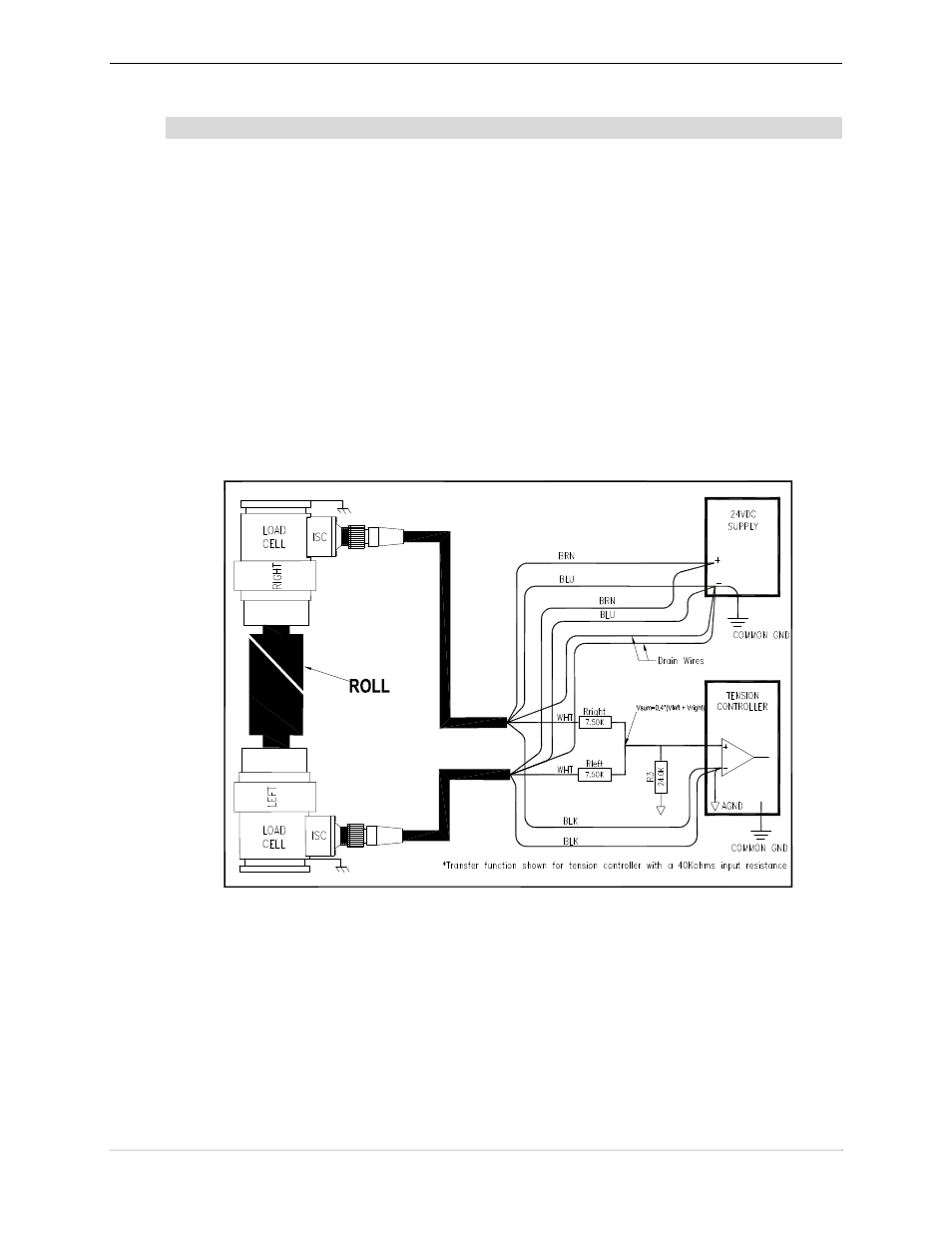
In the most common approach, a pair of equal-valued resistors are used in the classic resistive
summer circuit. A third resistor acts as a ground referred load which receives the combined signal
from each of the loadcells. The load resistance may be part of the analog input circuit’s input
impedance, but may also be supplemented by a fixed resistance for improved load resistance
stability.
In the following schematic using the resistance values shown, the equation for the summed signal
is:
V
sum
= 2/5 (V
left
+ V
right
)
The resultant voltage for 10 volts applied to V
left
and V
right
would therefore be 8V.The maximum
load impedance experienced by each loadcell’s output stage would be 7.5K ohm, necessitating that
each loadcell amplifier be capable of 1.3 mA of load current.
Figure 7 ISC Summing Amplifier
The final approach to be discussed is to “stack” the two loadcell outputs by wiring the analog
outputs to be “series aiding”.
P
AGE
22
OF
42