ADTRAN 6530 User Manual
Page 8
8
61225001L1-5D
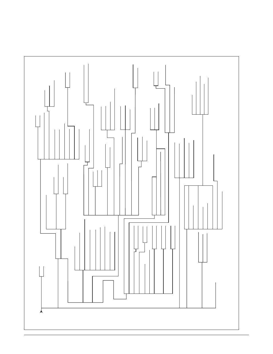
Figure 5. Express 6530 Menu Tree
Software Optioning
The menu tree in Figure 5 illustrates the path to every
provisioning, performance monitoring, and test access
point in the Express 6530 menu system.
1. Unit Information
Main Menu
2. Provisioning
2. L
T
1. NT
1. PN127
2. V
.54
2. Disable
1. Enable
1. -15.
Threshold in dB
0. Disabled
2. Inverted
1. Normal
2. DTE Driven
1. Permanent Of
f
2. DTE Driven
1. Permanent Of
f
1. -999.
T
ime out
0. Disabled
2. T
est
Driven
1. Permanent Of
f
1. -100. Delay in Seconds
0. Disabled
2. From DTE, ETC (circuit 1
1
3)
1. From DCE,
TC (circuit 1
1
4)
2. Inverted
3. Auto
1. Normal
1. -127.
Threshold in dB
0. Disabled
0. -225. Delay in ms
5. Performance History
(15-minute and 24-hour Registers)
6. T
erminal
Mode
*
Enter a new value for N from 3 to 36, where the aggregate rate (Kbps) = (Nx64) + 8
**
From 00h to 1Fh for static condition of NF
AS spare bits (0, 0, 0, Sa4, Sa5, Sa6, Sa7, Sa8)
3. Status
4. T
est
2. [Local Unit] G.703
3. [Remote Unit] SHDSL
1. [Local Unit] SHDSL
2. G.703 Loopback
T
ype
3. G.703 Services Loopback
T
ype
Service 1.-31.
4. Nx64K Loopback
T
ype
1. SHDSL
Loopback
T
ype
2. T
ransparent
1. Dual Sided
3. Non-transparent
2. Permanent On
1. Permanent Of
f
3. R
T
S Driven (V
.24)
4. R
T
S Driven (C107 Emulation)
2. Permanent On
1. Permanent Of
f
3. Sync Mode
2. Permanent On
1. Permanent Of
f
3. Sync Mode
2. SNR Margin
Alarm
Threshold (dB)
1.
Aggregate Rate (Kbps)*
3. Loop
Attenuation
Alarm
Threshold (dB)
2. Nx64K ETC
1. Internal
3. G.703 RX Clock
2. SHDSL
Options
1. Unit Options
3. G.703 Options
5. T
est
Options
4. Nx64K Options
NTU
LT
U
1. Unit Mode
2. Cross-Connect Map
3. L
T
Mode Clock Source
4. Circuit ID
5. Date and
T
ime
8. Local Management
9. Change Password
7. Download Firmware
6. Reset Factory Defaults
2. SHDSL
Remote Loopback
1. SHDSL
Local Loopback
3. SHDSL
BER
T
4. G.703 Local Loopback
5. G.703 BER
T
6. G.703 Services
8. Nx64K Remote Loopback
Send Inband Pattern
9. Nx64K BER
T
7. Nx64K Local Loopback
1. Inactivity
Alarm Delay (Secs)
3.
TX Clock Polarity
2.
TX Clock Source
5. CTS (Circuit 106)
6. R
TS to CTS Delay (ms)
4. R
TS (Circuit 105)
1. Permanent On
2. DTE Driven
1. Permanent On
2. DTE Driven
8. DTR (Circuit 108/2)
9. RLSD (Circuit 109)
7. DSR (Circuit 107)
2. G.704 CRC-4 Multiframing
1. IDSN-PRA
V3
3. G.704 Idle Pattern
from 00h to FFh
5. Network Spare Bits Pattern**
4. Network Spare Bits Insertion
6. Customer Spare Bits Insertion
7. Customer Spare Bits Pattern**
9. Customer E-Bit Generation
8. Customer RAI Generation
2. [Local Unit] G.703 Port
1. [Local Unit] SHDSL
Port
3. [Local Unit] G.703 Services
5. [Remote Unit] SHDSL
Port
4. [Local Unit] Nx64K Port
2. Customer
T
ransparent
1. Dual Sided
3. Customer Non-T
ransparent
5. Network Non-T
ransparent
4. Network
T
ransparent
1. In-Band Loopback Protocol
2. G.703 Services Pattern Detection
3. Nx64K In-Band Pattern Detection
2. Inband Loopback Options
1. Loopback
T
ypes
3. Loopback
T
ime Out (Minutes)
5. Pushbuttons (All)
4. BER
T
T
est Pattern Polarity
6. SHDSL
Port Select Pushbutton
7. V
.35 RL
(Circuit 140)
9. V
.35
TI (Circuit 142)
8. V
.35 LL
(Circuit 141)
Service 1. -31.
NOTE: