3 led indicators, 4 rear panel, 5 hardware installation – INTELLINET NETWORK 560900 24 Ports Gigabit + 4 Gigabit SFP PoE+ Web Management Ethernet Switch User Manual User Manual
Page 9
8
2.3 LED Indicators
The LED Indicators present real-time information of systematic operation status. This table
provides description of LED status and the meaning.
Table 1-1 LED Indicators
LED
Status
Description
On
Power on
Power
Off
Switched to Off or disconnected from
power source
On
Link
Flashing
Data activating
Link / ACT
Off
No device is attached
On
Port is linked to powered device
PoE
Off
No powered device is connected
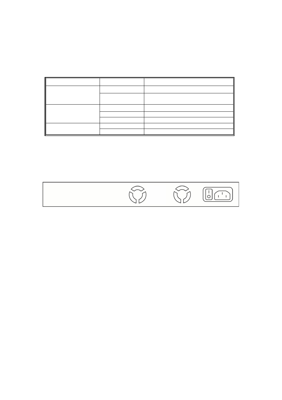
2.4 Rear Panel
The 3-pronged power plug is on the rear panel of the switch as shown as below. This is
reserved for AC power input.
2.5 Hardware Installation
The switch is typically mounted in a 19” rack, installed in an IT room or other secured
place. Make sure all the power cables, Ethernet cables, mounting screws and such are
prepared and installed as described below, including clearance for adequate ventilation.
Ports 1–24 are copper ports, requiring UTP/STP cable. These ports are also PoE ports,
requiring CAT 5/5e or above for the PoE application.
Ports 1–4 are also the combo SFP ports.
Ethernet cable requirements
The wiring cable types for data transmission are as below.
10 Base-T: 2-pair UTP/STP Cat. 3, 4, 5 cable, EIA/TIA-568 100-ohm (max. 100m)
100 Base-TX: 2-pair UTP/STP Cat. 5 cable, EIA/TIA-568 100-ohm (max. 100m)
1000 Base-T: 4-pair UTP/STP Cat. 5 cable, EIA/TIA-568 100-ohm (max. 100m)
The wiring cable types for data transmission and power delivery in any speed should be
Cat5 or above.