Cashco B2 User Manual
Page 3
IOM-B2
3
CAUTION
To prevent damage to body, use soft jaws when
placing body in a vise. Position so that vise closes
over the fl ats on lower end of body.
SECTION VI
VI. MAINTENANCE
A. General:
1. Maintenance procedures hereinafter are
based upon re mov al of the regulator unit
from the pipeline where in stalled.
2. Owner should refer to owner's procedures for
removal, handling, cleaning and disposal of
non reuseable parts, i.e. gaskets, etc.
3. Refer to Figure 2 for Model B2 basic reg u -
la tor and Figure 1 for the diaphragm sub as -
sem bly.
B. Diaphragm Replacement - Model B2:
1. Securely install the body (1) in a vise with
knob (4) directed upwards.
2. Relax range spring (15) by turning knob (4)
CCW until rotation comes to a complete stop.
NOTE: It is not necessary to remove the knob
(4) before removing the spring chamber (6)
from the body (1).
3. Remove spring chamber (6) by grasping the
fl ats and turning CCW. Upon removal, the
range spring (15), range spring clip (16), and
spring button (5) should remain inside the
spring cham ber.
4. Remove diaphragm subassembly (7) con-
sist ing of the actuator nut (7.3), diaphragm
(7.1), ac tu a tor post (7.2), ac tu a tor gasket
(7.4), ac tu a tor o-ring (7.5). Remove di a -
phragm gas ket (10).
5. Remove actuator nut (7.3) and separate all
parts of the diaphragm subassembly (7).
6. Clean body (1) diaphragm fl ange surface
and all re us able parts according to owner's
procedures. Do not scratch di a phragm
gas ket seat ing sur face. NOTE: On reg u-
la tors origi nally sup plied as “oxygen clean”,
Option-M, main tenance must in clude a level
of clean li ness equal to Cash co's clean ing
stan dard #S-1134. On regulators originally
suppled for Sanitary Service, maintenance
must in clude a level of clean li ness equal to
Cash co clean ing stan dard #S-1576. Contact
factory for details.
7. Inspect and replace any necessary parts.
NOTE: Use only parts man u fac tured and
sup plied by Cashco, Inc. for these products.
See Section VIII.
8. Reassemble
di
a phragm subassembly (7) by
plac ing the actuator gasket (7.4), di a phragm
(7.1), and actuator o-ring (7.5) over the
threads of the actuator post (7.2). Place a
thread sealant com pound on the threads of
the ac tu a tor post (7.2) prior to installing the
actuator nut (7.3). Install ac tu a tor nut (7.3)
and tighten to the fol low ing torque value: ALL
SIZES: 15 Ft-lbs (20 Nm).
9. Place the diaphragm gas ket (10) onto the
body (1) diaphragm fl ange. Place di a phragm
sub as sem bly on top of the gasket (10).
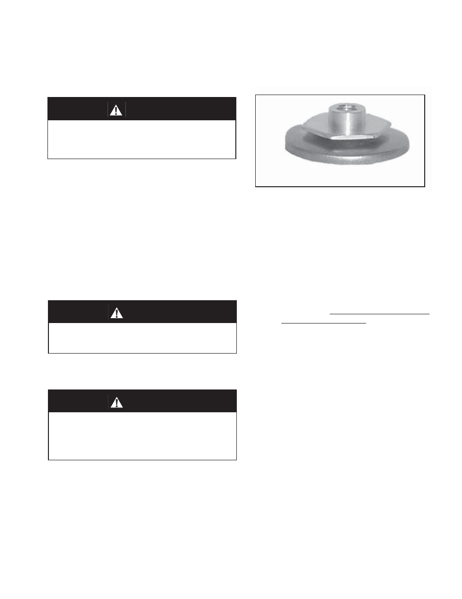
Figure 1: Diaphragm Subassembly
WARNING
SYSTEM UNDER PRESSURE. Prior to performing
any maintenance, isolate the regulator from the sys-
tem and relieve all pressure. Failure to do so could
result in personal injury.
WARNING
SPRING UNDER COMPRESSION. Prior to removing
spring chamber, relieve range spring compression
by turning the knob CCW until rotation comes to a
complete stop. Failure to do so may result in fl ying
parts that could cause personal injury.
2. If the regulator and system are to both be shut
down, slowly close the inlet (upstream) block
valve. Close the outlet (downstream) valve only
if reg u la tor re mov al is required.