Cashco DA0 User Manual
Page 2
IOM-DA0
2
IV. PRINCIPLE OF OPERATION
1. The pilot receives steam from the upstream tapping
in the side of the main regulator body and passes
it thru to the cover dome. When a loading pres-
sure – P
Load
– is applied into the top of the cover
dome, the outlet controlled pressure – P
2
– will
balance at approximately .90 – .98 of the loading
pressure - P
L
. (NOTE: Fluc tu a tions in P
1
– Inlet
Pressure will cause a deviation in P
2
– Outlet
Pressure due to inverse sym pa thet ic ratio effect.)
See Section VIII.
V. STARTUP
1 Start with the block valves closed.
2. Adjust the loading system pressure control de vice
so that main regulator is trying to be con trolled at 0
psig pressure. (For spring loaded pilots, relax the
range spring compression by turning the adjusting
screw CCW.)
3. If it is a “hot” piping system, and equipped with
a bypass valve, slowly open the bypass valve
to preheat the system piping and to allow slow
ex pan sion of the piping. Closely monitor outlet
(down stream) pressure via gauge to ensure not
over-pressurizing. NOTE: If no bypass valve is
in stalled, extra caution should be used in starting
up a cold system; i.e. do everything slowly.
4. Crack open the outlet (downstream) block valve
to approximately 10% full open.
5. Slowly open the inlet (upstream) block valve to
about 25% open. Adjust the loading system pres-
sure control device setpoint pressure upwards
until the main valve is fl owing. Observe the outlet
pressure gauge to ensure not overpressurizing.
6. Continue to slowly open the inlet (upstream) block
valve until fully open.
7. Continue to slowly open the outlet (downstream)
block valve, especially when the downstream pip-
ing system isn’t pressurized. If the outlet (down-
stream) pressure exceeds the desired pres sure,
close the inlet block valve and go to Step 2. Close
bypass valve approximately 25%, and re peat
pro ce dure.
8. When
fl ow is established steady enough that the
outlet (downstream) block valve is fully open, begin
to slowly close the bypass valve if installed.
2. Movement occurs as pressure variations register
on the stop plate. The registering pressure is the
outlet, P
2
, or downstream pressure. The loading
pressure fl uid op pos es plug move ment. As outlet
pres sure drops, the loading pressure push es the
stop plate down, opening the port; as outlet pres-
sure increases, the plug pushes up and the port
opening closes.
3. A loss of loading pres sure while inlet pressure is
imposed will cause the regulator to fail close.
SECTION IV
SECTION V
CAUTION
DO NOT HYDROSTATIC TEST THROUGH AN IN STALLED
UNIT; ISOLATE REGULATOR FROM TEST. The "OUTLET
RATING" as printed on the name plate is the rec om mend ed
“upper op er at ing limit” for the sens ing di a phragm. Higher
pres sures could cause internal dam age. In ad di tion, note
on the nameplate that the Inlet and Outlet pres sure and
temperature ratings are at different levels.
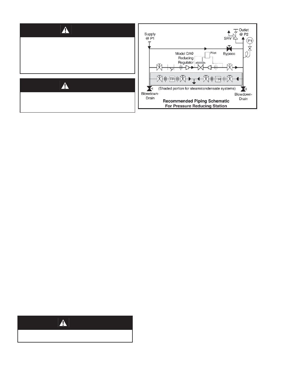
CAUTION
Installation of adequate overpressure pro tec tion is recom-
mended to pro tect the reg u la tor from over pres sure and
all down stream equip ment from dam age in the event of
regulator failure.
CAUTION
Do not walk away and leave a bypassed reg u la tor unat-
tended!