Stage 2 - wiring & electrical, 1 - fitting the control panel in the casing, Screws screw positioning holes – CAME Ati-S324 Kit User Manual
Page 10: Green connector point fastening screws
9
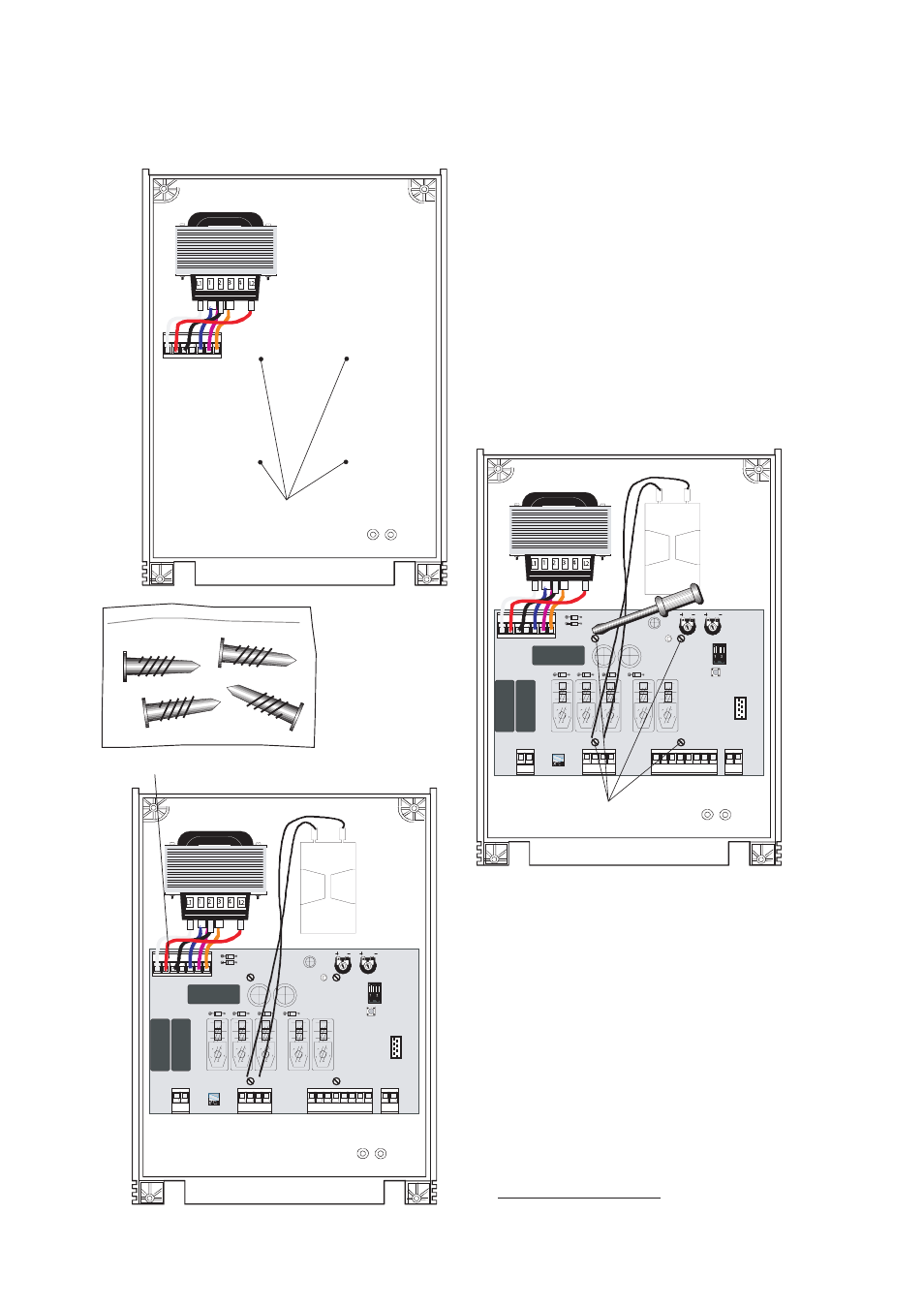
Screws
Screw positioning holes
Green connector point
Fastening screws
Securely fasten the control panel PCB to the
casing with the screws supplied.
Plug the green connector from the transformer to
the PCB ensuring that it connects the correct way.
NB FROG Series Motors: connect the black wires
coming out of the board to one capacitor.
STAGE 2 - WIRING & ELECTRICAL
2.1 - Fitting the Control Panel in the Casing
This manual is related to the following products: