Leveling valve orientation at full extension – Hellwig Air 6299 User Manual
Page 12
13. When satisfied with position of level-
ing valve and linkage has been checked for
proper operation and clearance, mark hole
location to attach leveling valve bracket to
crossmember. Drill (2) 1/4” holes and
install (2) 5/16” self tapping bolts to attach
bracket to crossmember.
Torque bolts to
10 ft-lb
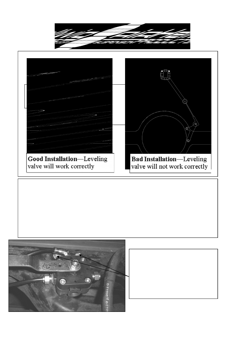
12. Reconnect shock absorbers to axle brackets and torque bolts to 60-70 ft-lb. IMPOR-
TANT— Raise vehicle frame until the wheels come off the ground and support frame on
jack stands. Note orientation of leveling valve linkage. The leveling valve arm and link
must NOT be in line when the suspension is at full extension or the valve will not operate
properly. Ensure there is at least a 20 degree angle between the lever arm and linkage at
full extension . The leveling valve can be moved toward the passenger side frame rail to
increase this angle. The leveling valve MUST be RECHECKED at compression and nomi-
nal ride height if the leveling valve is moved to ensure that the arm and linkage will not
contact the vehicle or any of its components.
Good Installation—Leveling
valve will work correctly
Minimum 20 deg An-
gle between linkage
and lever arm main-
tained at full extension
Bad Installation—Leveling
valve will not work correctly
Lever arm and linkage point at
each other at full extension
which will result in damage to
lever arm, valve and linkage.
Correct by moving leveling
valve toward passenger side
frame rail until minimum angle
Leveling valve orientation at full extension
6299 ( R-6299)
02/26/2010