Hellwig Air 6299 User Manual
Page 10
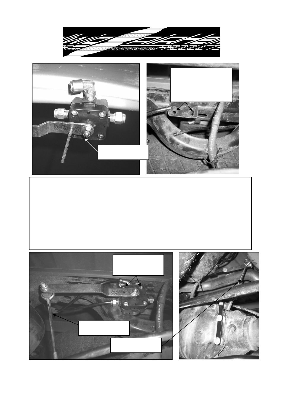
10. Attach leveling valve to bracket as shown using 1/4” nylon locknuts and
washers. Tighten to 7 ft-lb.
Attach leveling valve linkage pins to valve and axle
bracket in orientation shown. Make sure that the axle bracket and linkage pin
will not interfere with brake lines. Relocate brake lines as required. Tighten nuts
to 8-10 ft-lb. Assemble linkage as shown in photos and clamp leveling valve
bracket to frame crossmember in location shown so that linkage geometry
matches photo.
DO NOT drill mounting holes at this time. Center leveling
valve by inserting a 11/64” drill bit through hole in arm and body of leveling
valve. When satisfied with linkage geometry, REMOVE drill bit.
Center lever arm on
valve with 11/64” drill
Locate slotted holes for valve
as shown.
Clamp bracket to
frame for initial installation.
DO NOT DRILL ANY
HOLES AT THIS TIME.
Linkage to be angled as
shown for initial layout.
Link must be attached as
shown for initial layout.
Attach leveling valve to
bracket using long studs
at top of valve.
6299 ( R-6299)
02/26/2010
- Pro Series Silence (2 pages)
- Pro Series 61610 (2 pages)
- Pro Series 61901 (2 pages)
- Pro Series 61905 (2 pages)
- Pro Series Standard (2 pages)
- Load Pro Series LP 25 (2 pages)
- Load Pro Series LP 15 (1 page)
- Load Pro Series 9640 (1 page)
- Load Pro Series 9655 (2 pages)
- EZ 1000 (1 page)
- EZ 991 (1 page)
- Front Helper Spring 14114 (1 page)
- Front Helper Spring 14139 (2 pages)
- Helper Spring 820 (1 page)
- Helper Spring 979 (3 pages)
- Helper Spring 982 (2 pages)
- Helper Spring 1250 (1 page)
- Helper Spring 1251 (1 page)
- Helper Spring 1510 (2 pages)
- Helper Spring 1515 (1 page)
- Helper Spring 1520 (2 pages)
- Helper Spring 1555 (1 page)
- Helper Spring 1560 (1 page)
- Helper Spring 1565 (1 page)
- Helper Spring 1901 (3 pages)
- Helper Spring 1902 (2 pages)
- Helper Spring 1906 (1 page)
- Air 6005 (6 pages)
- Sway Bar 5909 (3 pages)
- Air 6006 (7 pages)
- Air 6012 (8 pages)
- Air 6014 (7 pages)
- Air 6016 (7 pages)
- Air 6090 (21 pages)
- Air 6091 (9 pages)
- Air 6102 (7 pages)
- Air 6106 (6 pages)
- Air 6108 (8 pages)
- Air 6107 (6 pages)
- Air 6110 (9 pages)
- Air 6111 (8 pages)
- Air 6118 (7 pages)
- Air 6150 (6 pages)
- Air 6154 (6 pages)
- Air 6210 (6 pages)