Gardner Bender B2555 Series Electric Sidewinder Bender User Manual
Page 8
8
2. If side marking occurs, or loading IMC or EMT is a problem,
pressure against the conduit during the bending process must
be decreased. To decrease the squeeze ( pressure ), loosen
both set screws and turn both adjusting bolts one-half turn
counter-clockwise. Tighten both set screws and bend one piece
of conduit to test the adjustment. If side marking still occurs,
repeat the procedure.
NOTE: Both adjusting bolts MUST be in contact with the bender
frame.
15.0 MAINTENANCE
WARNING: ALWAYS disconnect power supply before removing
any guards or covers and before servicing this bender. Failure to
do so may result in serious injury or death.
1. The Gear Box is filled with oil at the factory and should not
require periodic flushing. If the Gear Box is opened for repair,
flush by filling the unit with an AGMA #7 oil. Next, run the unit
with no load for 3 minutes. Then, drain and refill the unit with 28
fluid ounces of an AGMA #7 oil such as the ones listed below.
Amoco – Amoco Worm Gear Oil
Chevron – Cylinder Oil 460X
Exxon – CYLESSTIC TK460
Mobil – 600 W Cylinder Oil
Shell – Sun Gear Oil 7C
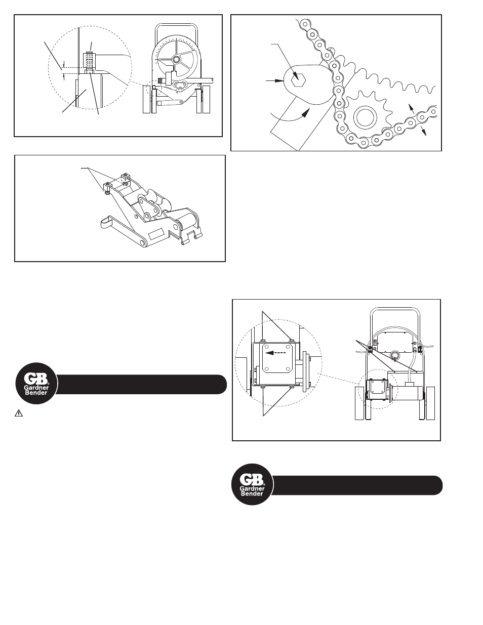
2. To inspect FRONT #60 chain tension:
• Remove front cover plate.
• To adjust, loosen hex bolt with 3/4 wrench and rotate chain
tensioner toward chain as shown until chain moves no more
than a total of 1/4". See Figure 16.
• Grease chain periodically with a good quality MP grease.
Figure 15
Both Adjusting
Bolts Must Contact
Bender Frame
3. To inspect REAR #40 chain tension:
• Check chain tension after an initial break-in period of 2 - 3 hours
of use and tighten per the instructions below. See Figure 17.
Thereafter, inspect monthly.
• Remove the chain guard by taking out the 2 mounting screws.
• Loosen 8 bolts ( 4 on top and 4 on bottom ) that hold the gear
box in position.
• To tighten chain, move the gear box to the left and
re-tighten bolts.
• For correct tension, chain should deflect approximately 1/8".
NOTE: Be sure to keep the gear box and motor in line with
the bender.
• Grease chain periodically with a good quality MP grease.
16.0 STUB-UP BENDING
INFORMATION AND CHARTS
To locate bending marks and springback of 15, 30, 45, 60, and 90
degree bends for a desired stub:
1. Check Chart A, B, or C for deduct length. Note that minimum stub
length is deduct length plus 2".
2. Measure and mark desired stub length on conduit ( stub length
mark ). Subtract “Deduct Length” from this mark and make
a second mark ( bending mark ). See Fig 18a and 18b. Place
bending mark at front edge of shoe hook. See Figure 18c.
Check Chart A, B, or C for springback of desired degree of
bend. Bender should be advanced to this degree to obtain
desired degree of bend.
To Tighten
Chain
Figure 17
4 Bolts on
Bottom
4 Bolts on Top
Chain Guard
Mounting
Screens
Bender Leg
Figure 14
1/2"
Adjusting
Bolt
Set
Screw
Starting
Location of
Adjusting
Bolt
Rotate Chain
Tensioner Upward
to Tighten Chain
Figure 16
1/4" Max
Hex Screw
Chain
Tensioner