Gardner Bender B2555 Series Electric Sidewinder Bender User Manual
Page 5
5
8.0 GROUNDING INSTRUCTIONS
WARNING: ELECTRIC SHOCK HAZARD! Only connect the bender to a 20 AMP GFCI protected circuit. Do NOT modify the plug which
is provided with the unit. Failure to follow these warnings can result in serious injury or death.
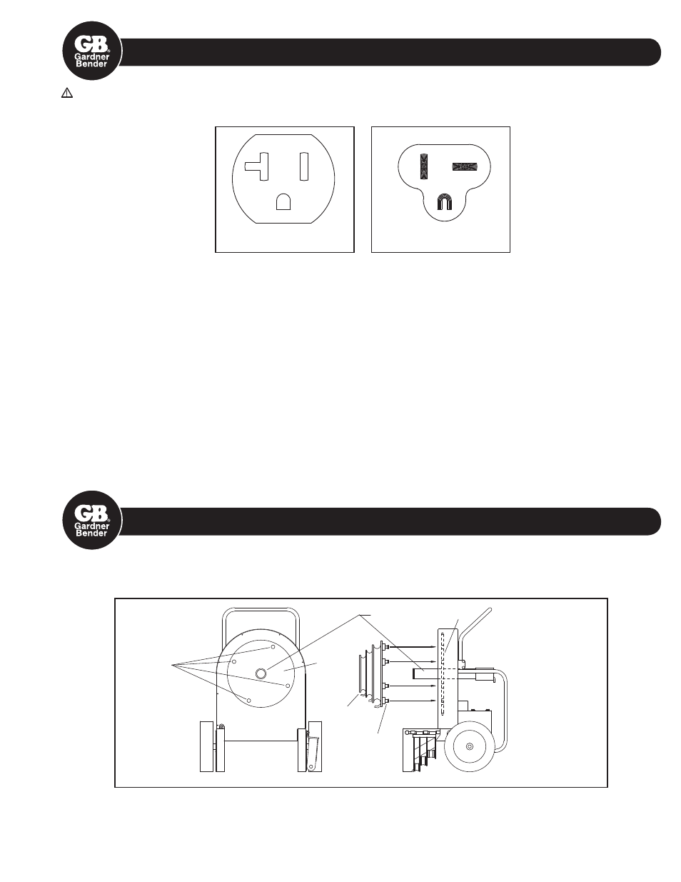
Figure 3
Figure 4
RECEPTACLE
PLUG
In the event of a malfunction or breakdown, grounding provides a path of least resistance for electric current to reduce the risk of
electric shock. The bender is equipped with an electric cord having an equipment grounding conductor and a grounding plug. Only
connect the bender to a 20 AMP GFCI protected receptacle which is properly installed and grounded to meet all applicable electrical
codes. Do NOT use an adapter.
Do NOT modify the plug provided. If it will not fit the receptacle, have the proper receptacle installed by a qualified electrician.
Improper connection of the equipment grounding conductor can result in risk of electric shock. The conductor with insulation hav-
ing an outer surface that is green with or without yellow stripes is the equipment grounding conductor. If repair or replacement of the
electric cord or plug is necessary, do not connect the equipment grounding conductor to a live terminal.
Check with a qualified electrician or service personnel if the grounding instructions are not completely understood, or if in doubt as to
whether the bender is properly grounded.
Use only 3-wire extension cords that have 3-prong grounding plugs and 3-pole receptacles that accept the bender’s plug.
Repair or replace damaged or worn cord immediately.
This bender is intended for use on a circuit that has a receptacle that looks like the one illustrated in Figure 3 above. The bender has a
grounding plug that looks like the plug illustrated in Figure 4 above.
9.0 MOUNTING BENDING SHOES
Choose desired shoe size and type ( RIGID, IMC, EMT, or 40 mil PVC coated RIGID ) and slide shoe onto the main drive sprocket
shaft. See Figure 5 below.
Sprocket
Shaft
Main Drive
Sprocket
Main
Drive
Sprocket
Bending
Shoe
Drive Studs
Drive Holes
Figure 5
Figure 6
Next, align the four drive studs on the back of the shoe with the four drive holes in the main drive sprocket.
Push the shoe onto the main drive sprocket shaft. See Figure 6.