Gardner Bender B2555 Series Electric Sidewinder Bender User Manual
Page 6
6
COULD result in minor personal injury or property damage.
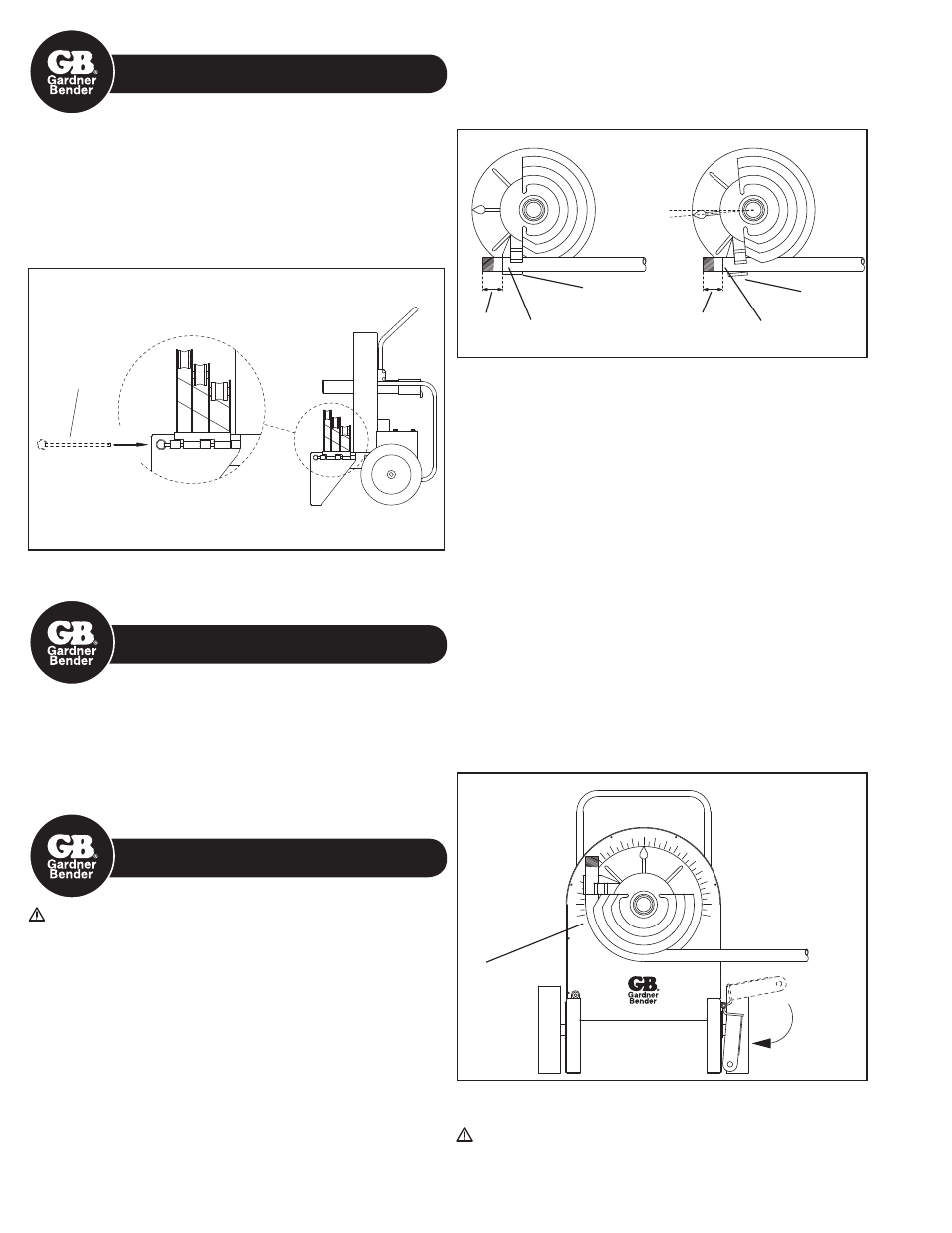
10.0 MOUNTING SUPPORT
ROLLERS & SUPPORT UNITS
Choose the desired support unit for corresponding shoe size
and type ( RIGID, IMC, EMT, or 40 mil PVC coated RIGID ). The
appropriate size and type of support unit MUST be used with the
corresponding shoe size and type.
Mount the support unit on the right leg of the bender as you face the
unit. Secure the support unit with the quick release hinge pin. See
Figure 7.
Quick
Release
Hinge Pin
Figure 7
11.0 Mounting Instructions for
Greenlee
®
Shoes and Attachments
Bending shoes and attachment from Greenlee
®
555
®
and 555
Classic
®
R, E, I ( RIGID, EMT, IMC ) and 40 mil PVC coated RIGID
benders with serial number PL and AAJ will fit the B2555 bender.
All B2555 bending shoes and attachments will fit Greenlee
®
555
®
R, E, I benders with PL and AAJ serial numbers.
* Greenlee
®
555
®
and 555 Classic
®
are registered trademarks of Greenlee/Textron.
12.0 GENERAL BENDING
INSTRUCTIONS
DANGER: NEVER operate this bender in an explosive
atmosphere. Injury or Death may occur.
Bending instructions for:
1/2" thru 2" RIGID conduit
1/2" thru 1-1/4" EMT conduit
1/2" thru 1-1/4" IMC conduit
1/2" thru 2" 40 mil PVC coated RIGID conduit
1/2" thru 2" schedule 40 pipe
See pages 5 and 6 for mounting shoes and support units. Be sure to
match the appropriate shoe with its corresponding support unit.
1. Mark pipe/conduit to desired length. Note that a minimum of
2" from the end of the conduit to the front edge of the hook is
required to eliminate flattening the end of the pipe/conduit. See
Figure 8a.
NOTE: Stub-up and Offset Dimensions can be found on the
Bending Charts on pages 8 thru 10 of this manual or on the bending
instructions decal on top of each bender.
2. Rotate the bending shoe 5 to 10 degrees below the 0 ( zero )
degree setting, as shown in Figure 8b below.
3. After marking the pipe/conduit, place it into the bender. See Figure
8a. The pipe/conduit should slide over the correct size support
unit, through the shoe groove and into the hook. The bending
mark should be at the front ( OUTSIDE ) edge of the hook. See
Figure 8a.
4. Using the remote hand unit ( pendant ), place the “Bend/Unload”
switch in the “bend” position. Press the “Jog” button and advance
the bender. Be sure to check the alignment of the bending mark
as the rotating shoe locks the pipe/conduit into position. Advance
the bender shoe to desired degree of bend. When the pointer on
the shoe reaches the desired degree of bend, release the “Jog”
button and the bender will stop. See Figure 9.
NOTE: Due to springback in pipe/conduit, some over bending is
necessary to achieve the desired degree of bend. See page 9 or
the bending instruction decal on top of each bender for approximate
springback compensation figures.
5. To release the pipe/conduit, place the “Bend/Unload” switch in
the “Unload” position. Press the “Jog” button and reverse the
shoe far enough to release the conduit. Then, rotate the support
unit out of the way. See Figure 9. The pipe/conduit can now be
removed.
WARNING: The pipe/conduit should be under control when
unloading. Failure to do this may result in injury or death.
2"
minimum
Figure 8a
Figure 8b
Bending
Mark
Hook
0°
5°
Bending
Mark
Hook
2"
Minimum
90° Bend
Shown
Figure 9
Rotate