Introduction, St100 modbus basic setup, Setting the st100 for modbus operation – Fluid Components International ST100 Series Modbus User Manual
Page 5: Introduction st100 modbus basic setup
ST100 Series Modbus Operation
Fluid Components International LLC
1
Introduction
The ST100 offers MODBUS as one of its digital communication protocol, but unlike the the other digital communication protocols MODBUS only
offers set up and configuration for the totalizer variable.
The ST100 MODBUS physical layer uses the asynchronous RS485 serial port of the ST100. There is no high speed MODBUS over Ethernet.
The ST100 offers the two basic traditional transmission serial interface modes: RTU and ASCII message coding.
The ST100 offers the process variable parameters (value) in floating point form, which are organized as single or double precision floating point
registers. There are two groups or registers used, the 4000 series and the 5000 registers, they both can be accessed using MODBUS 03, and 04
function codes. For details see table 1.
ST100 Modbus Basic Setup
For details on connecting the ST100 see Appendix B of the “Operation & Maintenance Manual” for the ST100 Series Thermal Mass Flow Meter,
document number 06EN003400.
Setting the ST100 for Modbus Operation
Note:
If the ST100 was ordered from the factory as a Modbus device, the factory will have configured the instrument for Modbus,
and it will not be necessary to do any instrument configuration.
The ST100 PC configurator is use to select the communication protocol.
Connect the PC with the configurator software to the ST100 USB port using FCI’s USB cable (P/N 022646).
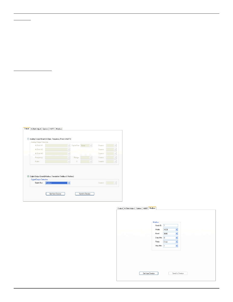
To configure the ST100 for Modbus invoke the ST100 Configurator,
then from the tree menu, on the left side, select “Configurator”,
then select the “Output” tab. In the Output Tab select “DigitalOut-
put Board” and then from the pull down menu select “Modbus“.
To change configuration for the Modbus by using ST100, select
“Modbus” tab and set Node ID, Mode, Baud, Data Bits, Parity
and Stop Bits.