Procedure – Fluid Components International ST110_ST112_STP110_STP112 VeriCal User Manual
Page 5
ST100 Series VeriCal Operation Manual
Fluid Components International LLC
3
Procedure
• Verify that the VeriCal pressure gauge indicates 25.0 PSIG (+/- 0.20 PSIG). Note: using the exact pressure levels allows one to compare the cur-
rent findings to the FCI Factory findings and any subsequent findings.
• Allow the instrument to stabilize by sustaining the pressure for a minimum of 5 minutes. Observing the flow and temperature reading stability
on the ST100 Configurator to verify that the instrument has come to equilibrium.
• Record the VeriCal pressure as indicated on the regulator assembly pressure indicator and the ST100 data that is shown on the Configurator:
RefR, dR, TCdR, Temperature, Flowrate and optionally the output current across a precision 250Ω resistor.
• Repeat this process for 50, 75 and 100 PSIG pressures.
• The recorded values are the instrument’s in-situ baseline calibration readings. All future verification readings will be compared to these baseline
values and should be within 2-5% of the Field Baseline Data readings.
• It is advisable to complete one more round of “Field Check Data” to establish a pattern of repeatability for this specific combination.
Note: This step is not mandatory, but it will help to understand the VeriCal system and what can be expected for future verifications.
• The ST100 Configurator application can now be closed.
• Place probe assembly back into the correct location in the center of the process piping as indicated in the installation section of the operation
manual.
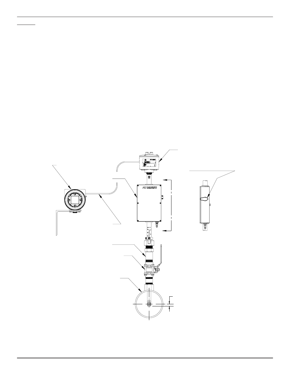
Normal Mounting Configuration
.50
A
A
OPEN
PLUG VALVE
(SHOWN IN CLOSE POSITION)
VIEW A-A
VERICAL BOX
ASSEMBLY
LOCAL ENCLOSURE
REMOTE
ENCLOSURE
(SYSTEM ELECTRONICS)
C01061-2-1
INTERCONNECTING
REMOTE CABLE
PACKING GLAND
ASSEMBLY WITH
1 1/4" NPT
BALL VALVE
PROCESS PIPING