Introduction, Theory of operation, Setup – Fluid Components International ST110_ST112_STP110_STP112 VeriCal User Manual
Page 3
ST100 Series VeriCal Operation Manual
Fluid Components International LLC
1
Introduction
This manual guides the user of the VeriCal instrumentation through an initial gathering of in-situ baseline data. This baseline line data will then be
compared to data gathered during similar future verification processes to determine if the system is operating within factory specifications.
Theory of Operation
The VeriCal system uses a sonic nozzle to consistently control the amount of compressed air (or nitrogen) injected onto the thermal flow transducer
located on the end of the probe assembly. It is critical to use the same gas for subsequent VeriCal runs to ensure repeatability.
The operating principle of the sonic nozzle requires the total or absolute pressure on the high side of the nozzle to be greater than 20.0 PSIA. The
pressure difference between the high side of the sonic nozzle and the process pressure (low-pressure side of the nozzle) must be greater than 2:1.
When these two requirements are met, a repeatable flow is injected onto the thermal flow transducer.
Setup
FCI Recommends that this procedure be run during the commissioning process of the instrument to determine an initial installed baseline calibration
and to document any installed offset from the factory VeriCal baseline.
Frequency: Every 18 months minimum, every six months is recommended. After the process has been performed a couple times the customer should
determine the required verification frequency based upon the process conditions.
This procedure makes the assumption that the instrument has been installed and is completely functional in the normal operating condition and
orientation. The customer should also have access to the factory VeriCal calibration certificate.
Note: All standard safety procedures must be followed during the verification process. This procedure assumes the standard
packing gland process connection. Your process connections may vary. It is critical to establish a Field Baseline upon
receiving your ST100. This will ensure a greater likelihood of repeatability and establish a history of the VeriCal data.
• Apply the proper input power and allow for a 30-minute warmup. It is critical that the electronics and the sensor be fully warmed and stable
prior to the VeriCal process. Failure to allow the proper warmup time can impact repeatability.
• Loosen the packing nut on the packing gland assembly until the internal packing is lose enough to allow the probe assembly to be retracted out
of the process and is recessed completely into packing gland assembly. Retract the probe assembly completely.
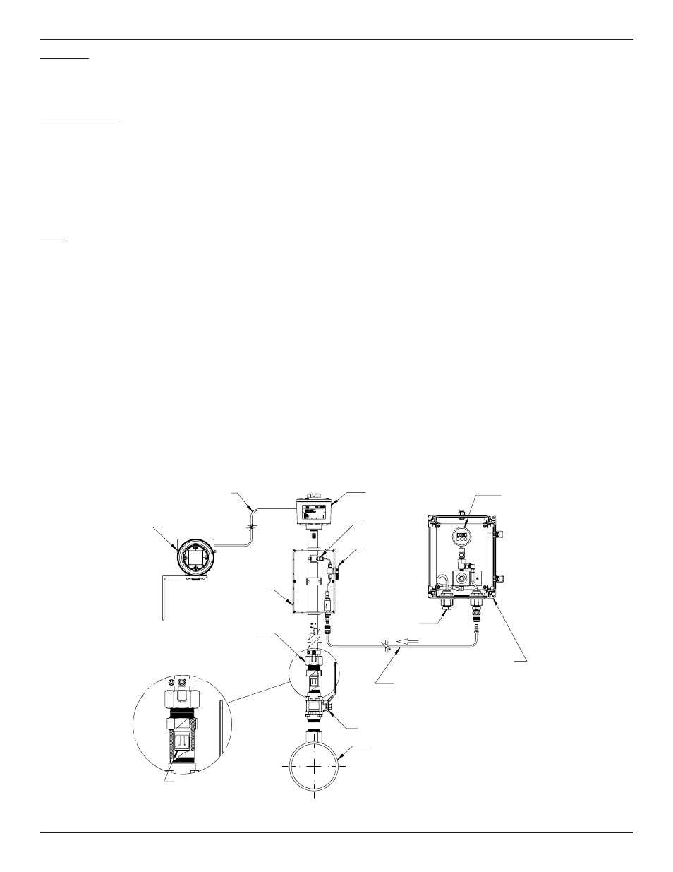
Retracted VeriCal Mounting Configuration
LOCAL ENLCOSURE
VERICAL BOX
ASSEMBLY
(SHOWN WITHOUT COVER)
INTERCONNECTING
REMOTE CABLE
PACKING GLAND
ASSEMBLY
WITH 1 1/4 " NPT
REMOTE ENCLOSURE
(SYSTEM ELECTRONICS)
PLUG VALVE
(SHOWN IN
OPEN POSITION)
INTERCONNECTING,
AIR HOSE.
1/8" FEMALE NPT,
AIR INLET
BALL VALVE
PROCESS PIPING
C01061-1-1
REGULATOR
ASSEMBLY
RETRACTED
PROBE ASSY
HIGH SIDE
PRESSURE
READING
SONIC NOZZLE