Step 2. wiring the hart instrument, Step 3. programming the hart instrument – Fluid Components International ST98 HART Option User Manual
Page 2
FLUID COMPONENTS INTERNATIONAL LLC
ST98 HART Option
This page is subject to proprietary rights statement on cover page
2
Doc. No. 06EN003323 Rev. D
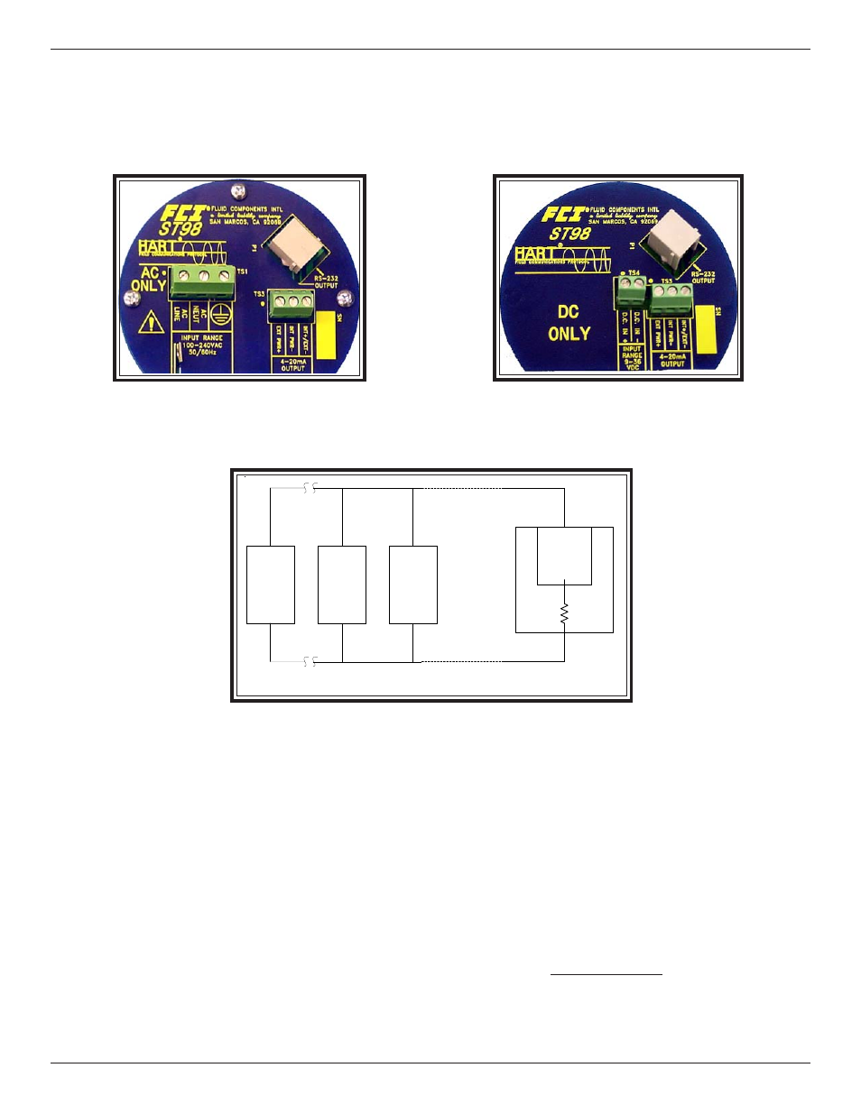
Step 2. Wiring the Hart Instrument
INPUT POWER - Follow the ST98 manual to connect power. The power is also connected per the face of the circuit board below.
OUTPUT SIGNAL - Connect the 4-20 signal output per the face of the circuit board below.
AC Power Input
DC Power Input
MULTIPOINT DROP LOOP OUTPUT:
ST
98H
-
X
ST
98H
- 1
ST
98H
- 0
POWER
SUPPLY
HART NETWORK
MASTER UNIT
INT + /EXT -
EXT
PWR +
-
+
X = 15 Maximum
Step 3.
Programming the Hart Instrument
Using the HART 275 Communicator with the ST98 Series:
Universal Commands (commands 0-33) can be accessed with no additional programming of the Customer’s 275 Communicator. This
means that they can read Flow Rate, Temperature and Totalizer values.
FCI Specific Commands (commands 128 and above) require that the Communicator be sent to a HART Foundation Programming
Center to have it programmed for the FCI specific commands. HART Programming Centers are capable of programming the Commu-
nicator to allow it to access all commands. This will allow the user to access all diagnostic and test functions available in the ST98.
To find a Programming Center nearest the user, access the HART Foundation Web site at www.hartcomm.org.