Fluid Components International MT91 Manual Installation User Manual
Page 2
FLUID COMPONENTS INTL
CHAPTER 2 - INSTALLATION
Model MT91 Multipoint Flowmeter
2 - 2
Doc. No. 003185 Rev. B
Verify Serial Numbers
Verify that the flow elements' serial number matches the flow transmitter serial number. A tag indicating the serial
number is located on the local and remote enclosures, see Figures A-2, A-3, and A-4.
When multiple flow elements connect to one flow transmitter, each flow element serial number has a suffix that
represents the flow element number. For example, if two flow elements connected to a flow transmitter have a base
serial number of 123, then the first flow element would have the serial number 123-1, and the second flow element
would have the serial number 123-2.
Prepare or Verify Flow Element Location
Mount the flow element at least 20 diameters downstream and 10 diameters upstream from any bends or interference
in the process pipe or duct to achieve the greatest accuracy.
Mount the flow element where the flow stream temperature is well above the saturation temperature of any of the
process gases. If a component of the process media is near its saturation temperature, it will probably condense on
the sensing points. Liquid on the sensing points will drive the flow measurement higher than actual.
The flow element’s shape is cylindrical with a diameter of 2 inches. The length is customer specified. The
recommended diameter for the clearance hole needed to mount the flow element is 2.03 inches. See Figure A-5 for
recommended process connection.
For optimum performance, prepare additional support at the end of the flow element for instruments exceeding 2 feet
in length. Refer to Figure A-5, and A-6 for recommended end support configuration.
Verify Dimensions
Verify the flow element and flow transmitter dimensions as shown in Appendix A.
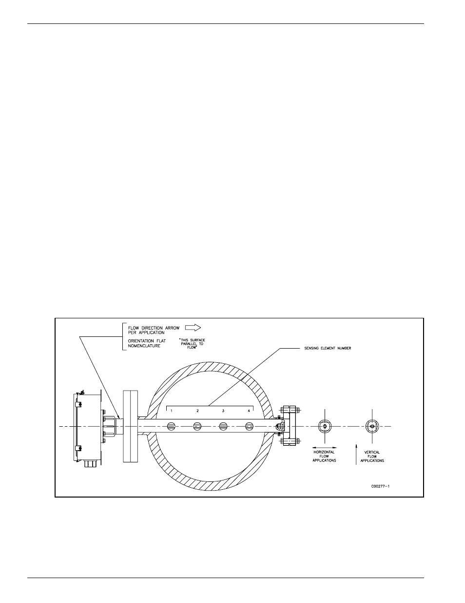
Verify Flow Direction for Flow Element Orientation and Placement
The flow element comes with a FLAT area machined on the flow element near the enclosure. Etched in the FLAT is
a FLOW ARROW indicating the direction of flow. See Figure 2-1.
Figure 2-1. Flow Element Showing FLAT Area
Align the flow element during installation so the FLAT is parallel, to the direction of the process media flow, and
the FLOW ARROW points in the direction of process media flow. Failing to install the flow element correctly will
reduce the accuracy of the flowmeter.