Fluid Components International MT91 Manual Troubleshooting User Manual
Page 5
Doc. No. 003185 Rev. B
5 - 5
Model MT91 Multipoint Flowmeter
CHAPTER 5 - TROUBLESHOOTING
FLUID COMPONENTS INTL
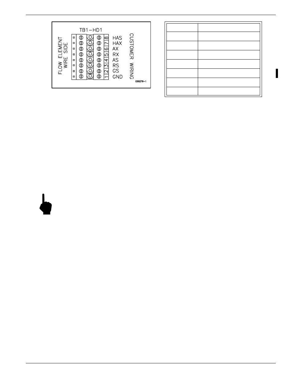
3, but not to Table 5-2, the cable is defective or the flow element is misswired. Replace cable and recheck
resistances. If resistances are still off, contact Customer Service.
If the measured values do not correspond to Table 5-3, then the sensing element is defective. Contact Customer
Service.
Check the Analog Outputs
Before using this utility, the analog outputs must be correctly configured. Refer to Chapter 3 for setting up the
analog outputs. For signal connections, refer to Figure 2-2 and Table 2-2 in Chapter 2.
1.
Go to menu level 3.2.1 (Diagnostics
Þ
Output Tests
Þ
Analog Out Test).
2.
Select the desired channel.
3.
Enter the percent of full scale.
Note:
For outputs configured 0 to 5 Vdc and 0 to 10 Vdc, the output should be the selected percentage of the
full scale value. For outputs configured as 4 to 20 mA, the output should be 4 mA plus the selected
percentage of 16 mA.
4.
If the correct value is not obtained, refer to Chapter 3 to re-calibrate the output channel.
5.
If the calibration is unsuccessful, remove and replace assembly 015231.
Check the Relays
Refer to Chapter 3 for setting up the relay outputs. For signal connections, refer to Figure 2-2 and Table 2-2 in
Chapter 2. This utility will operate the relays regardless of their configuration.
1.
Go to menu level 3.2.2 (Diagnostics
Þ
Output Tests
Þ
Relay Test).
2.
Select the desired relay.
3.
The present state of the relay is displayed on the second line. Press the appropriate key to change the state of
the relay.
4.
To observe the output, connect an ohmmeter between the relay contacts of interest (refer to Figure 2-2 and
Table 2-2).
5.
If the relay fails to operate, remove and replace assembly 015235.
Run the Calibration Test
See Chapter 3 for a full description of the function of the calibration test and for instructions on scheduling
automatic calibration tests. Test for shifts in calibration parameters or unbalance sensing points.
Figure 5-2. TB1-HD1 Terminal Connector
Terminal No.
Approximate Resistance
2 to 3
1000 ohms
2 to 4
1000 ohms
2 to 5
1000 ohms
2 to 6
1000 ohms
7 to 8
220 ohms
4 to 6
0 ohms
3 to 5
0 ohms
Table 5-3. Resistance at TB1-HD1 Terminal Connector
If the measured resistances correspond to Table 5-