Fluid Components International MT91 Manual Delta R Parameters User Manual
Appedix d. mt91 delta r parameters, 8 6 f 1
Doc. No. 003185 Rev. B
D - 1
Model MT91 Multipoint Flowmeter
APPENDIX D - MT91 DELTA R PARAMETERS
FLUID COMPONENTS INTL
5.1.3 Verify Setup Outputs
[1] = Channel 1
[2] = Channel 2
PortUnit[1] 0 = Flow 1 = Temperature
PortUnit[2] 0 = Flow 1 = Temperature
Out Head[1] Hexadecimal Notation
Out Head[2] Hexadecimal Notation
Zero[1]
Zero output setting at either zero (0) or minimum
flow. (e.g. 4mA represents either 0 or minimum
flow)
Zero[2]
Span[1]
High point of output signal.(e.g. 20mA represents
high point)
Span[2]
5.1.4 Verify Setup Communication
Comm Mode 0 = EIA-232C 1 = EIA-422
2 = EIA-485
Comm Rate 0 = 4800
1 = 9600
2 = 19.2K
Comm Prot 0 = Protocol 1 1 = Protocol 2 2 = Protocol 3
485 Addr
Explanation of Parameters and Code
5.1.1 Verify Setup Flow
Flow Units
Customer Specified Unit
Flow Heads Hexadecimal Notation
Area Unit
Customer Specified Unit
Area
Area of Customer Pipe or Duct
TC Ena
Temperature Compensation Enabled
Corr Ena
Correction Enabled
Offset Ena
Offset Enabled
Filter
Filter Strength (See Chapter 3)
Density
Standard Density of Customer Media in LBM per
cubic feet.
Flow Fac
Flow Factor
5.1.2 Verify Setup Temperature
Temp Type Units used during calibration.
Temp Heads Hexadecimal Notation
Appedix D. MT91 Delta R Parameters
For each instrument there are “MT91 Delta R Parameters” sheets and a 4-20mA look up table inserted in the rear
page protector. Appendix D explains the codes found on the Delta R Parameters sheets. A sample of both the Delta
R Parameter sheet and the 4-20mA look up table follow the explanations.
Above each column is a menu level code. When verifying parameters, access the menu level and then scroll down
through the menu until the value in question appears on the screen. For example, to view the parameter “dRmin 1”,
press HOME, 5, 2, 3, and 1. (Verify
Þ
Verify Cal
Þ
Flow
Þ
Limits). Scroll down by pressing ENTR until “dRmin 1”
appears on the screen.
The instrument uses internal units of Standard Feet per Second and degrees Fahrenheit. Therefore, all values on this
sheet are in Standard Feet per Second. Refer to "Verify Standard vs. Actual Conditions" in Chapter 5 to convert
actual readings to standard readings.
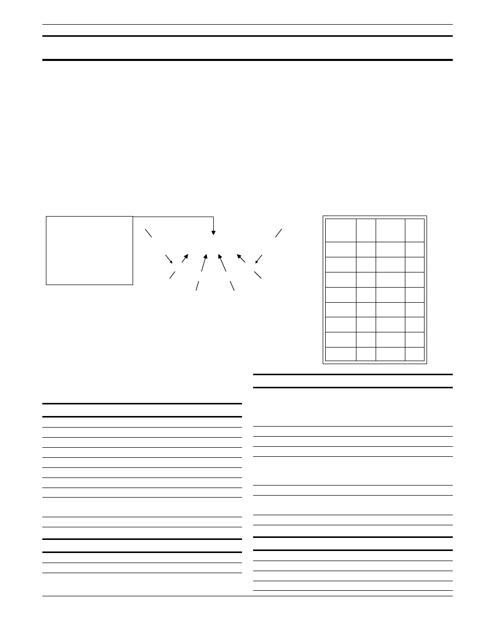
In menu levels 5.1.1 and 5.1.3 active sensing points are designated by hexadecimal notation. Use the following
diagram and table to decipher which sensing points are active. For example, the number 0003 in hexadecimal
notation means sensing points 1 and 2 are active.
Group
Code
Hex
#
Group
Code
Hex
#
'0000
0
1000
8
'0001
1
1001
9
'0010
2
1010
A
'0011
3
1011
B
'0100
4
1100
C
'0101
5
1101
D
'0110
6
1110
E
'0111
7
1111
F
8 6 F 1
1 0 0 0
0 1 1 0
1 1 1 1
0 0 0 1
G r o u p 4
This hexidecimal
notation is found on the
Delta R Parameter Sheet
and on the Display.
This code indicates that
sensing points
1,5,6,7,8,10,11, and 16
are active.
S e n s i n g
Point 1
0 = O f f
1 = O n
Group 1 represents sensing points 1,2,3, and 4.
Group 2 represents sensing points 5,6,7,and 8.
Group 3 represents sensing points 9,10,11, and 12.
Group 4 represents sensing points 13,14,15, and 16.
G r o u p 3
G r o u p 2
G r o u p 1
S e n s i n g
Point 16
C 0 0 2 9 8 - 1