Gf90/gf92 hart menu tree, Step 3. programming the hart instrument – Fluid Components International GF90_GF92 User Manual
Page 3
Doc. No. 06EN003339 Rev. -
3
GF90/GF92 HART OPTION
GF90/GF92 HART INSTALLATION AND OPERATION MANUAL
FLUID COMPONENTS INTL
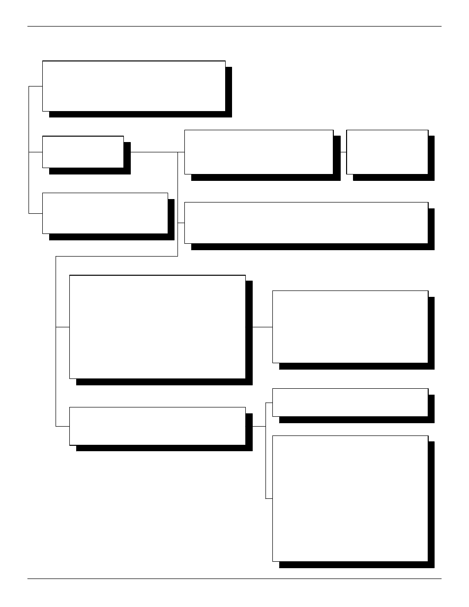
Step 3.
Programming the Hart Instrument
1 DEVICE SETUP
2 VOLT (Displays actual process value, i.e. flow)
3 LRV (Displays configured lower range value)
4 URV (Displays configured upper range value)
5 I OUT (Displays actual output current in mA)
6 % RANGE (Displays output current in percent of output span)
7 DATALOGGER
1 MAX. VALUE (Displays highest process
value since reset)
2 MIN. VALUE (Displays lowest process
value since reset)
3 RESET MIN/MAX (Reset the memory
holding min/max data)
1 LOOP TEST (Enter/Change loop current to a fixed value)
2 D/A TRIM (Connect a reference meter (5 digit) and
compensate for the inaccuracy in the output D/A
converter)
3 SENSOR TRIM
1 SIGNAL CONDITION
2 SENSOR TYPE (Enter Sensor type i.e. RTD, T/C,
mV, Ohm, Pot)
3 LRV (Enter lower range value)
4 URV (Enter upper range value)
5 DAMP (Enter damping value)
1 4 mA FIXED OUTPUT
2 20 mA FIXED OUTPUT
3 OTHER (Inter value of fixed current output)
4 END (Leave the menu)
1 SENSOR (mV Hi)
2 USL (Upper sense level
i.e. 1000 mV)
3 LSL (Lower sense level
i.e. 0 mV)
4 MIN SPAN (20 mV)
1 FACTORY TRIM (Offset and gain values are reset to
factory settings)
2 ONE POINT TRIM (Enter reference temp. value for a
non-calibrated sensor. Displays
measured temperature. In case
the ref temperatures are different,
enter this value.
3 TWO POINT TRIM (Enter 2 reference temperature
values. Displays actual measured
temp. In case the reference
temps are different, enter the
values. The gain is #1, the
function curve will change the
slope and not start in the zero
point)
4 VOLT. (Not used by FCI)
5 S. OFF. (This is the difference between the measured
and the reference value. Enter this value)
6 S. GAIN (Enter this value. This adjustment
corresponds to the 2-point trim. However
the function curve will start in the zero point.
MAIN MENU
1 DEVICE SETUP MENU
7 DATALOGGER MENU
3 DEVICE INFO
2.1
2.4
4.1
1 DISTRIBUTOR (Displays name Kamstrup)
2 MODEL (Displays name FlexTop HRT)
3 DEV ID (Displays device serial number)
4 TAG (Enter tag number (identify FlexTop HRT))
5 DATE (Enter date of choice, i.e. date of event)
6 WRITE PROT. (Displays status of write protection, NONE)
7 DESCRIPTOR (Enter description, i.e a location code)
8 MESSAGE (Enter a message, i.e. a warning)
9 FINAL ASMBLY NUM (Enter 8 digits, i.e. ref # identifying
sensor and transmitter during a
calibration session)
10 REVISION #'s (Displays the rev. #'s of the command set
(5), the FlexTop HRT(2) and the DD
software (3))
11 HART OUTPUT
1 POLL ADR (Enter the polling adr. for the FlexTop
HRT. Observe that poll adr = 0
automatically sets the FlexTop HRT in
analog mode, resulting in a mixed-signal
setup. If intent is to connect several
FlexTop's in Multi-drop mode, poll
addresses 1 to 15 must be used.
2 NUM PREAMS (Displays number of preamble
characters sent by master to ensure
sync with the slave device.
GF90/GF92 HART
MENU TREE
1 INPUT SETUP
2 OUTPUT SETUP
3 DEVICE INFO.
4 DIAG/SERVICE
1 INPUT SETUP
1 Signal Condition
1 UNDER LIM (Enter the output current for measurements LOWER than configured
range, i.e. if temp. falls below 0°C)
2 OVER LIM (Enter the output current for measurements HIGHER than configured
range, i.e. if temp. goes above 100°C)
3 SENS ERR (Enter the output current in case sensor fails.
2 OUTPUT SETUP*
11 HART Output
*This is a sub menu, where the out-of-range and sensor-burn-out can be entered.
4 DIAG/SERVICE**
1 Loop Test
3 Sensor Trim
**WARNING: To enter this menu, remove the loop from automatic
control. All trim adjustments can be carried out from
the configurator only - not from the FlexProgrammer.