Fluid Components International GF90_GF92 User Manual
Step 1. installation
GF90/GF92 HART OPTION INSTALLATION
AND OPERATION MANUAL
© Copyright 2002 Fluid Components Intl a limited liability company All Rights Reserved
Document
06EN003339 Rev. -
Step 1.
Installation
This manual is used to augment other instrument manuals when the Hart option is used. Use the following steps to
install the Hart Option for GF90/GF92:
24 Hour Factory Service Hot Line: 1 (800) 854-1993
Notice of Proprietary Rights
This document contains confidential technical data, including trade secrets and proprietary information which are the property of Fluid Components Intl
(FCI). Disclosure of this data to you is expressly conditioned upon your assent that its use is limited to use within your company only (and does not include
manufacture or processing uses). Any other use is strictly prohibited without the prior written consent of FCI.
Visit FCI on the Worldwide Web: www.fluidcomponents.com
1755 La Costa Meadows Drive, San Marcos, California 92069 USA - 760-744-6950 - 800-854-1993 - Fax 760-736-6250
European Office: Persephonestraat 3-01 5047 TTTilburg - The Netherlands - Phone 31-13-5159989 - Fax 31-13-5799036
1.
All the FCI transmitters that incorporate the HART protocol are set at the factory to polling address “0”. Users
should reset the polling address to match the needs of their network.
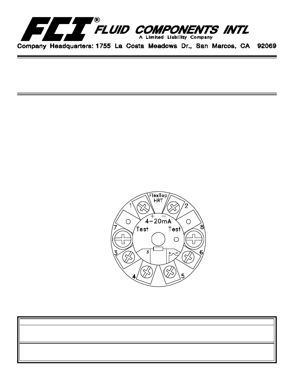
2.
At polling address “0”, the GF90/GF92 outputs a current of 4 - 20mA; at any other polling address, the GF90/GF92
outputs a fixed 4mA current; in compliance with the HART standard. A digital signal is provided with all polling
addresses.
3.
If the GF90/GF92is going to be used as a HART network transmitter, the polling address needs to be changed to
other than “0”. The power supply feeding the network must provide sufficient current to support the instruments in
the network.
Hart Module