7 maintenance and fault rectification, 1 maintenance, 2 remove interferences – Burkert Type 8112 User Manual
Page 23: 7maintenance and fault rectification
7
Maintenance and fault rectification
7
.1 Maintenance
If the instrument is used properly, no special maintenance is required
in normal operation.
7
.2 Remove interferences
The operator of the system is responsible for taking suitable measures
to rectify faults.
LEVEL SWITCH
8112 offers maximum reliability. Nevertheless, faults
can occur during operation. These may be caused by the following, e.
g.:
l
Sensor
l
Process
l
Voltage supply
l
Signal processing
The first measure to be taken is to check the output signal. In many
cases, the causes can be determined this way and the faults rectified.
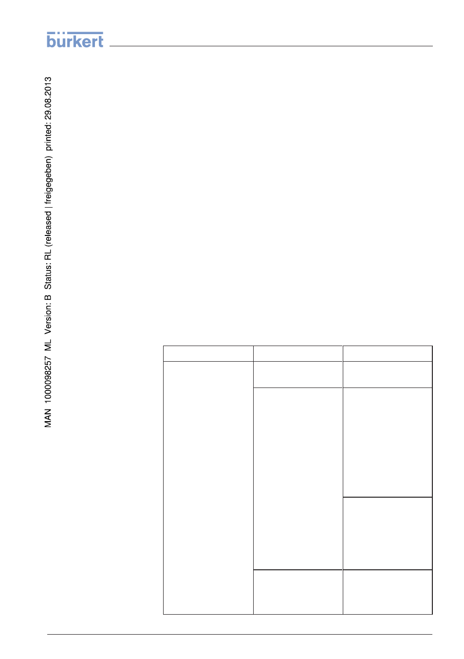
Error
Cause
Rectification
LEVEL SWITCH
8112
signals "covered"
without being submerged
(overfill protection)
LEVEL SWITCH
8112
signals "uncov-
ered" when being sub-
merged (dry run
protection)
Operating voltage too
low
Check operating voltage
Electronics defective
Press the mode switch. If
the instrument then
changes the mode, the
vibrating element may be
covered with buildup or
mechanically damaged.
Should the switching
function in the correct
mode still be faulty, re-
turn the instrument for
repair.
Press the mode switch. If
the instrument then does
not change the mode,
the electronics module
may be defective. Ex-
change the electronics
module.
Unfavourable installa-
tion location
Mount the instrument at
a location in the vessel
where no dead zones or
air bubbles can form.
Reaction when malfunc-
tions occur
Failure reasons
Fault rectification
Checking the switching
signal
LEVEL SWITCH
8112 • - Relay (DPDT)
23
7 Maintenance and fault rectification
32050
-
EN
-
120418