3 function chart – Burkert Type 8112 User Manual
Page 21
With the mode adjustment (A/B) you can change the switching
condition of the relay. You can set the required mode according to the
"F
unction chart" (A - max. detection or overflow protection, B - min.
detection or dry run protection).
With this DIL switch (3) you can set the switching point to liquids
having a density between 0.5 and 0.7 g/cm³ (0.018 and 0.025 lbs/in³).
With the basic setting, liquids with a density of > 0.7 g/cm³ (0.025 lbs/
in³) can be detected. In liquids with lower density, you must set the
switch to > 0.5 g/cm³ (0.018 lbs/in³). The specifications for the position
of the switching point relate to water - density value 1 g/cm³ (0.036 lbs/
in³). In products with a different density, the switching point will shift in
the direction of the housing or tuning fork end depending on the
density and type of installation.
Note:
Keep in mind that foams with a density > 0.45 g/cm³ (0.016 lbs/in³) are
detected by the sensor. This can cause faulty switchings particulary
when used as dry run protection system.
6
.3 Function chart
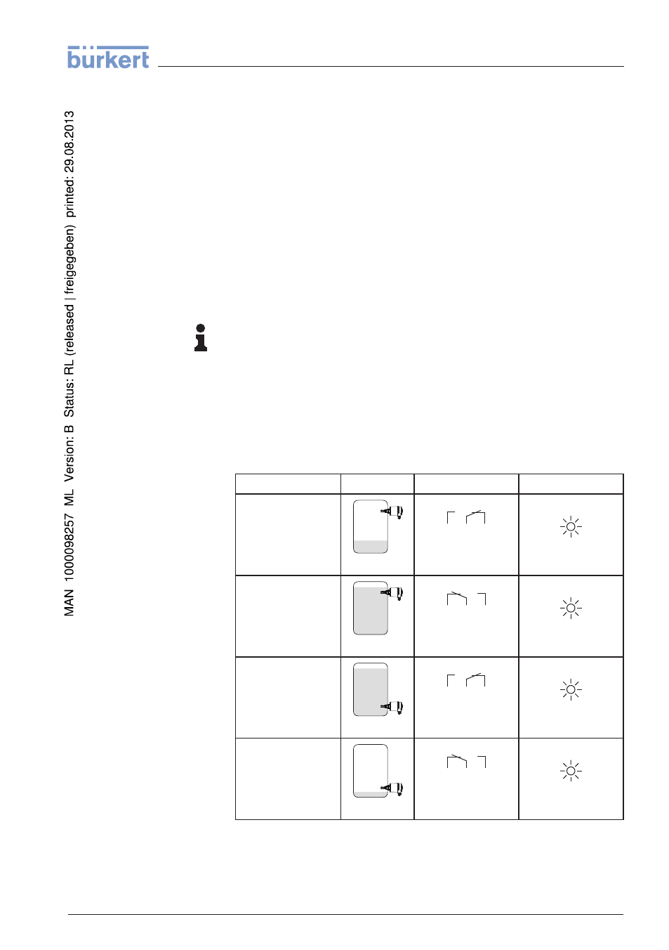
The following chart provides an overview of the switching conditions
depending on the adjusted mode and level.
Level
Switching status
Control lamp
Mode A
Overflow protection
5
3
4
(8)
(6)
(7)
Relay energized
Green
Mode A
Overflow protection
5
3
4
(8)
(6)
(7)
Relay deenergized
Red
Mode B
Dry run protection
5
3
4
(8)
(6)
(7)
Relay energized
Green
Mode B
Dry run protection
5
3
4
(8)
(6)
(7)
Relay deenergized
Red
Mode adjustment (2)
Sensitivity adjustment
(3)
LEVEL SWITCH
8112 • - Relay (DPDT)
21
6 Set up
32050
-
EN
-
120418