6 set up, 1 general information, 2 adjustment elements – Burkert Type 8112 User Manual
Page 20: 6set up
6
Set up
6
.1 General information
The figures in brackets refer to the following illustrations.
The switching condition of the electronics can be checked with closed
housing cover (control lamp). In the basic setting, products with a
density > 0.7 g/cm³ (0.025 lbs/in³) can be detected. For products with
lower density, the switch must be set to > 0.5 g/cm³ (0.018 lbs/in³).
On the electronics module you will find the following indicating and
adjustment elements:
l
Signal lamp (1)
l
DIL switch for mode adjustment - A/B (2)
l
DIL switch for sensitivity adjustment (3)
Note:
For test purposes, immerse the tuning fork of LEVEL SWITCH 8112
always in liquids. Do not test the function of LEVEL SWITCH 8112 with
your hand. This can damage the sensor.
6
.2 Adjustment elements
1
2
3
4
5
6
7
8
1
2
3
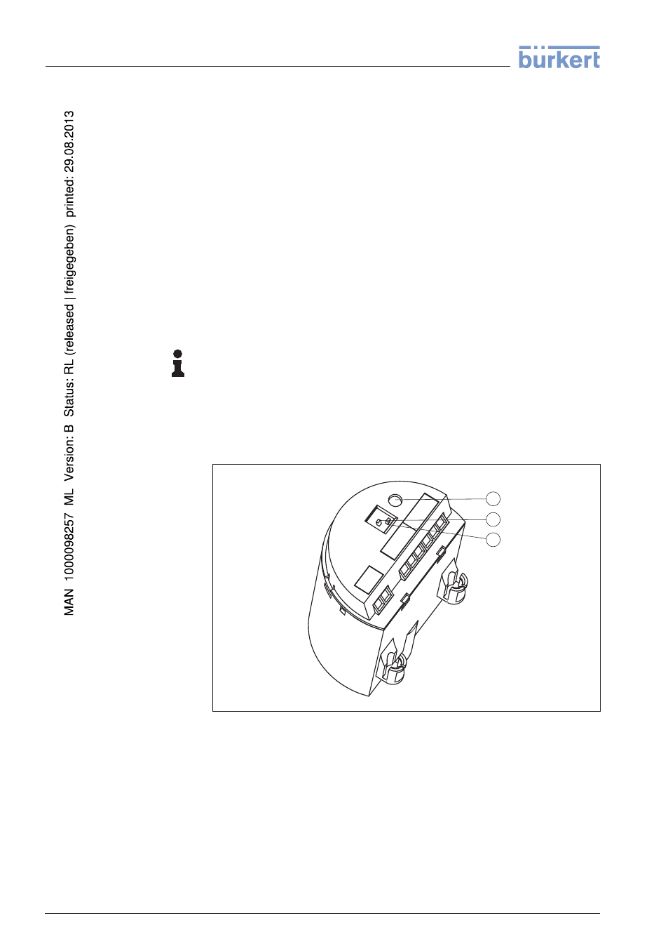
Fig. 12: Oscillator SWE60R - Relay output
1
Signal lamp (LED)
2
DIL switch for mode adjustment
3
DIL switch for sensitivity adjustment
Control lamp for indication of the switching status
l
green = relay energized
l
red = relay deenergized
l
red (flashing) = failure
Function/Configuration
Signal lamp (1)
20
LEVEL SWITCH
8112 • - Relay (DPDT)
6 Set up
32050
-EN
-120418