3 wiring plan, single chamber housing – Burkert Type 8112 User Manual
Page 18
5
Open the terminals with a screwdriver
6
Insert the wire ends into the open terminals according to the wiring
plan
7
Tighten the terminals with a screwdriver
8
Check the hold of the wires in the terminals by lightly pulling on
them
9
Tighten the compression nut of the cable entry. The seal ring must
completely encircle the cable
10 Screw the housing cover back on
The electrical connection is finished.
5
.3 Wiring plan, single chamber housing
3
5
1
2
4
R
2 0 - 2 5 3 V A C
2 0 - 7 2 V D C
A
B
L
N
1 2
3 4 5
6 7 8
0,5 g / cm3
0,7 g / cm3
3 4 5 6 7 8
+
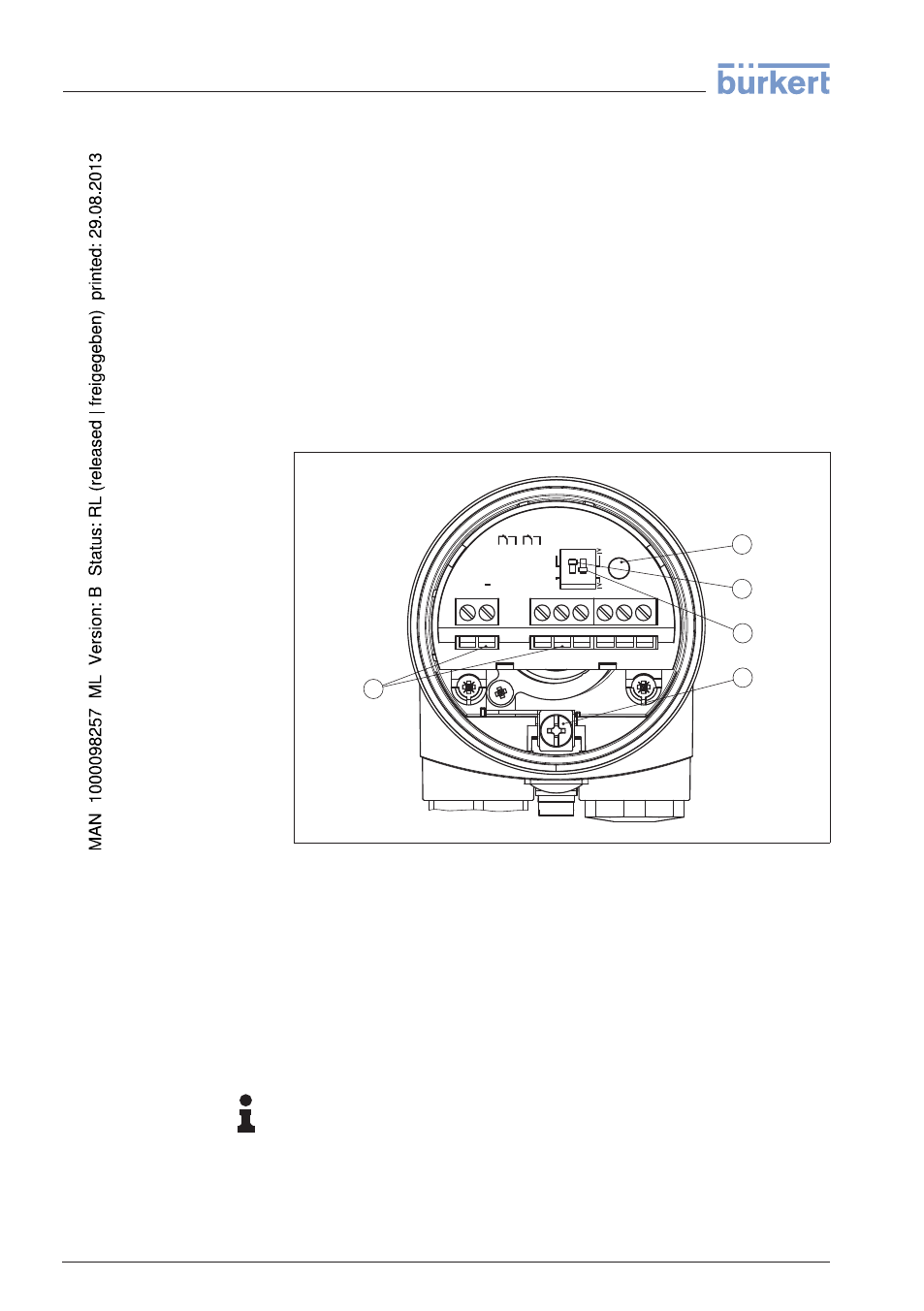
Fig. 10: Electronics and connection compartment, single chamber housing
1
Control lamp
2
DIL switch for mode adjustment
3
DIL switch for switching point adaptation
4
Ground terminal
5
Connection terminals
We recommend connecting LEVEL SWITCH 8112 in such a way that
the switching circuit is open when there is a level signal, line break or
failure (safe condition).
Information:
The relays are always shown in non-operative condition.
Electronics and connec-
tion compartment
Wiring plan
18
LEVEL SWITCH
8112 • - Relay (DPDT)
5 Connecting to power supply
32050
-EN
-120418