Burkert Type 8697 User Manual
Page 9
9
Particularsafetyinstructions
BVS 13 ATEX E104X / E087X
The electric circuits have the following parameter:
electric circuit limit switch
Upper end position: Terminals INI Top 1 +/-
Lower end position: Terminals INI BTM 1 +/-
Each:
Max. allowable input voltage (Ui)
20 V
Max. allowable input current (Ii)
60 mA
Max. allowable input power (Pi)
200 mW
Max. inner capacitance (Ci)
178 nF
Max. inner inductance (Li)
66
µF
electric circuit pilot valve
Pilot valve 1:
Terminals VALVE +/-
Max. allowable input voltage Ui and input current Ii
(use only value pairs that are displayed one below the other)
Voltage
value
[V] = ui
15 18
20
22
25
28
30
35
current
value
[A] = ii
0.9 0.44 0.309 0.224 0.158 0.120 0.101 0.073
Tab. 1: Value pairs input voltage - input current
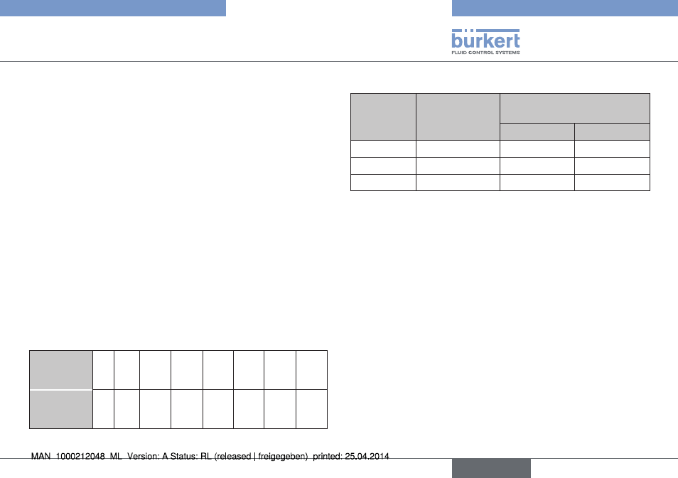
Max. allowable input power Pi
number of
pilot valves
max. allowable
output Pi
max. ambient temperature
type 8697
Pe99
Pe51
0
-
+55 °C
+60 °C
1
0.7 W
+55 °C
+55 °C
1
1.1 W
+50 °C
+50 °C
Tab. 2: Max. allowable input power
Max. inner capacitance (Ci)
negligible
Max. inner inductance (Li)
negligible
English