Mounting single valves, English – Burkert Type 6517 User Manual
Page 17
6516 / 6517 - 15
I
NSTALLATION
, I
NITIALISATION
AND
S
ERVICE
english
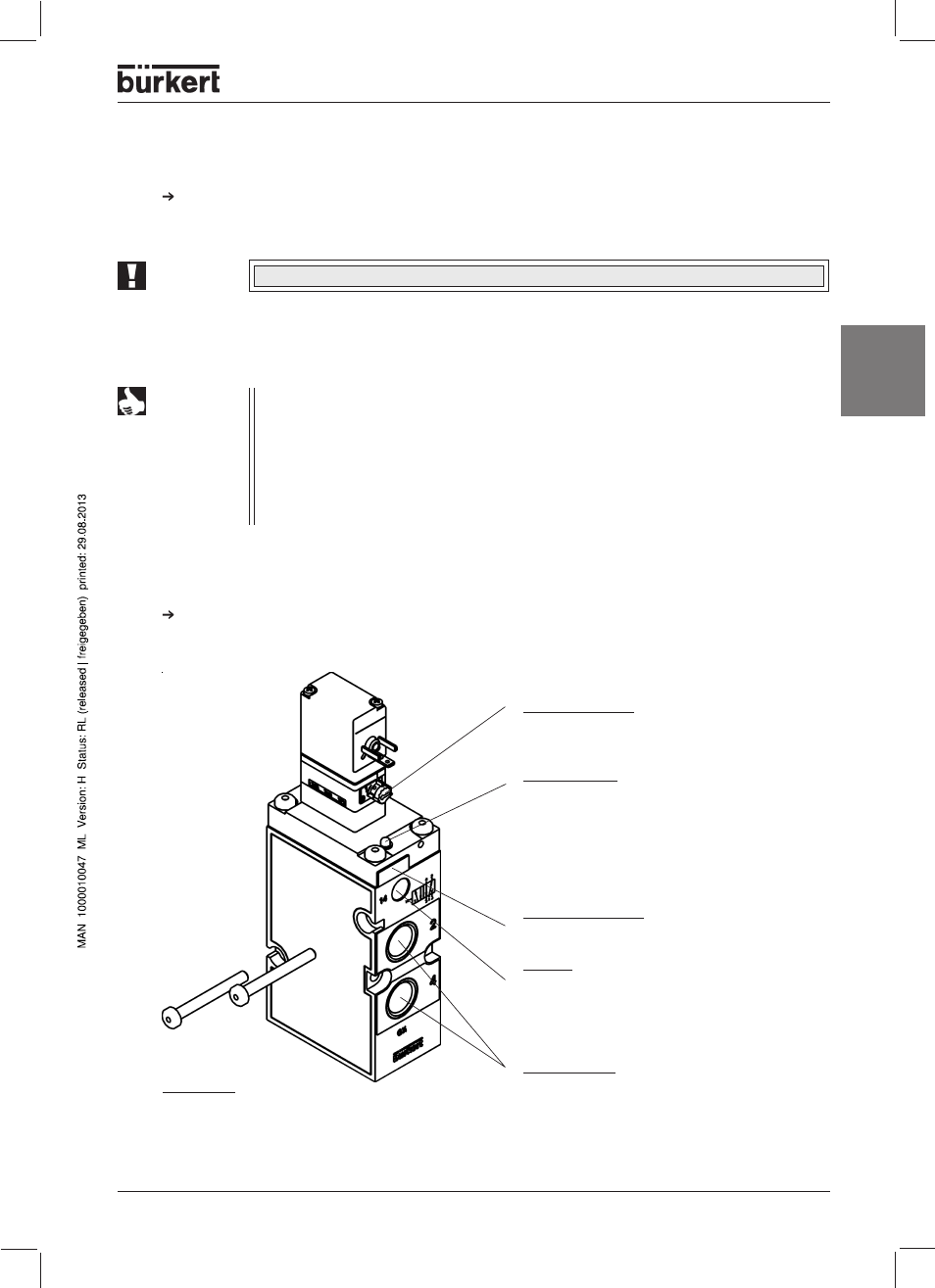
Mounting single valves
Fix the single valve directly to the wall using M4 screws.(Figure: Installation, Initialisation and Service -
Mounting single valves, Manual override,
Pneumatic position indicator)
NOTE
For plug-in connections, the hose lines must meet the following requirements:
• Minimum rigidity of 40 Shore D (to DIN 53505 or ISO 868);
• External diameter corresponding to DIN 73378 (max. permissible deviation ± 0.1 mm
from nominal dimension);
• Without burr, cut at right-angles and with undamaged circumference;
• The hose lines must be pushed into the plug-in connectors up to the stop.
Plug-in connections
Dismantling the plug-in connections
To release the line, press in the pressure ring and pull out the hose line.
Manual override
to operate the valve manually, turn the manual
override by 90° in the direction of the arrow
Indicating pin for indicating the pneumatic
position
With the valve not switched, the red indicating
pin can be pressed in. If the valve has been
switched, the indicating pin moves outwards,
and remains in this position. The indicating pin
must be pushed in again for every functional
test.
Designation plate (can be removed for
marking / engraving)
Port 14
• not used in the standard model
• used as an auxiliary pilot air connection
and as the connection for pneumatic
controls
Service ports
2 (B) and 4 (A)
M4 screws
for wall mounting
the single valve
Figure: Mounting single valve, Manual override, Pneumatic position indicator
ATTENTION!
When mounting, do not distort the valve body!