Flowline DL34 EchoPod User Manual
Page 20
20 of 29
EchoPod
31 MAR 11
MN204210
Rev B
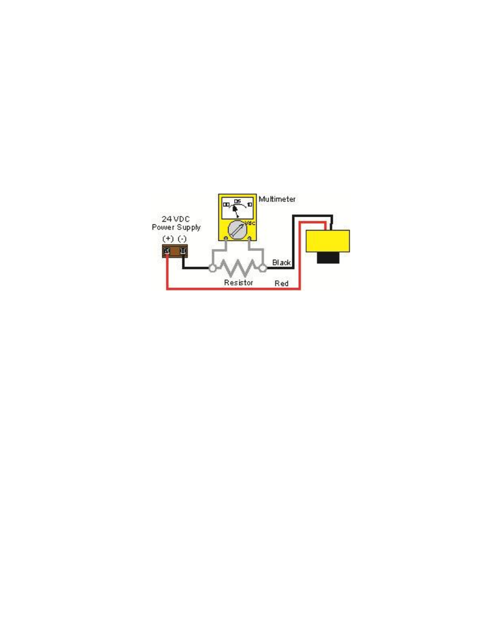
Voltage Output
EchoPod can be used as a 0 to 5 or 0 to 10 VDC output device. A resistor will need to be added to
the circuit to enable a voltage output (refer to the wiring diagram below).
0-5 VDC output
o Add a 250 Ohm resistor
o Actual output will be 0.8 to 5 VDC
0-10 VDC output
o Add a 500 Ohm resistor
o Actual output will be 2 to 10 VDC
When using WebCal, under Number of Pumps, select 4-20mA Transmitter Only to simplify the
configuration in WebCal.
Installation
The EchoPod should always be mounted perpendicular to the liquid surface and installed using the
provided Viton mounting gasket. Make sure that the fitting and transmitter threads are not damaged
or worn. Always hand-tighten the transmitter within the fitting. Perform an installed leak test
under normal process conditions prior to system start up. Note: The preferred mounting fitting for
the DL14 and DL24 series is the LM52-1400 (2” thread x 1” thread) reducer bushing.
Mounting Guide
1. Do not mount at an angle
2. Liquid should never enter the dead band
3. Side Wall:
a. For DL14 & DL24 Series - mount at least 2” from the side wall
b. For DL34 Series - mount at least 3” from the side wall
4. Do not mount where obstacles will intrude on sensor’s beam width
a. See Specifications on page 8
5. Do not mount in a vacuum
6. Avoid mounting in the center of a dome top tank.
7. In cone bottom tank, position the sensor over the deepest part of the tank.