Flowline DL34 EchoPod User Manual
Page 18
18 of 29
EchoPod
31 MAR 11
MN204210
Rev B
Wiring EchoPod
After you have finished positioning and mounting EchoPod, follow WebCal’s wiring diagram to
wire the sensor. A typical wiring diagram is shown above. Flowline recommends using a qualified
licensed electrician to wire EchoPod and your application’s components.
Note: Do not extend the White & Green wires beyond 15’.
Note: Configure your EchoPod with WebCal and use the wiring diagram button to view the
appropriate diagram. Each configuration will have its own unique diagram. The diagram above is
only a sample and should not be used as a wiring diagram.
Note: Once EchoPod is configured, isolate the white and green wires from active power to
prevent a short of the configuration circuit.
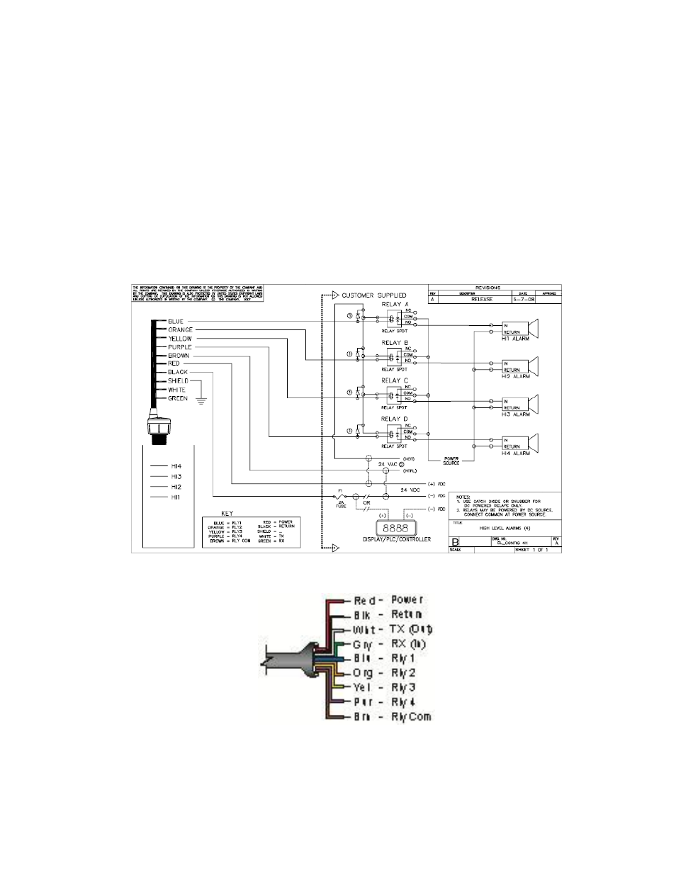
Wiring Diagram
Sample Wiring Diagram – Use WebCal to view appropriate wiring diagram
Wire Connections:
Red & Black
Red and Black leads are for connection to a 24 VDC power supply or to a 4-20 mA loop power
source. The red and black wires can be extended up to 1,000 feet using a 22 gauge or larger wire,
however do not extend the green and white wires.