Dsc4 – EBARA DSC4 User Manual
Page 7
26
INSTRUCTION MANUAL
Model
DSC4
(2) Protect surfaces of mating fl anges and the corners of spigot and socket.
(3) Cover the shaft threads to protect from damage after disassembly.
(4) After disassembly, apply temporary rust prevention to the machined surfaces such as
lifted surfaces, threads, shafts, etc.
(5) Be careful not to drop tools and parts into the sump pit.
(6) To protect against lost parts and mixing of parts with those from another machine,
provide cases for disassembled parts and store parts in cases.
(7) Store bolts in bags as a set.
(8) Do not disassembly the motor. If the motor requires disassembly, please contact us.
6.6 Replacing Components
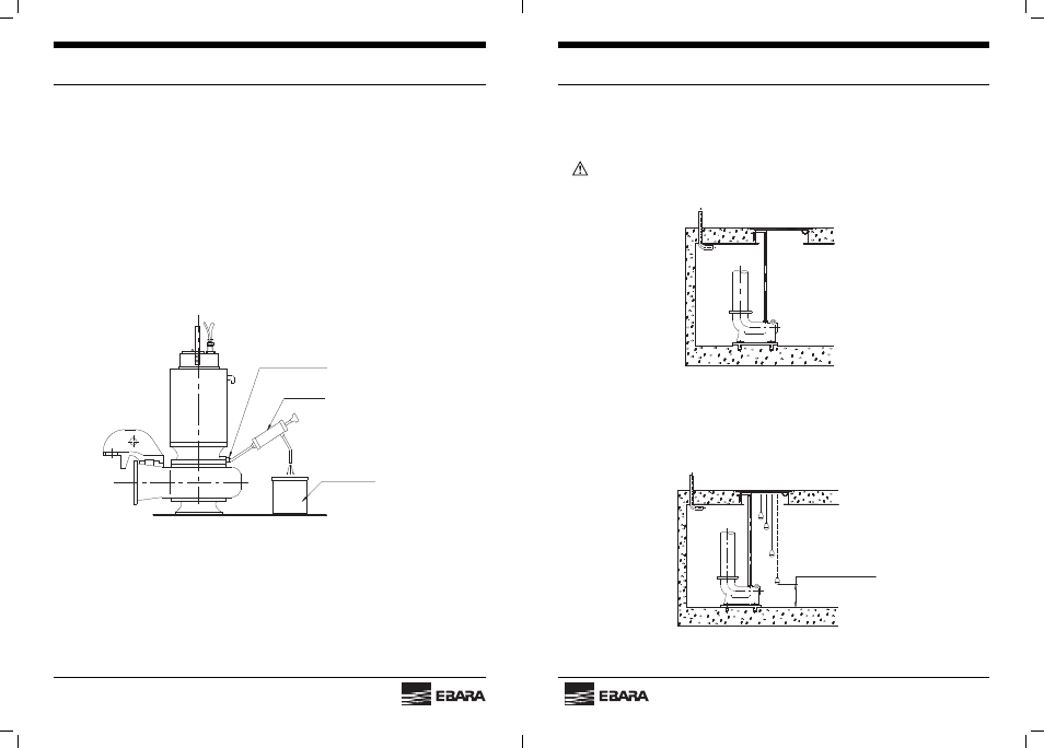
(1) Changing oil
Stand the pump in a vertical position, and unplug “oil drain” and “air vent”. Drain all oil
from the “oil drain” (In case of model “F” and “G”, using the oil pump.)
Fig. 22
Inspect the oil for water contamination. If the oil contains much water, mechanical seal must be
replaced.
After the oil has been inspected, pour oil (Turbine Oil ISO VG 32) through the “oil port”, until oil
overfl ows from “air vent”.
Put a sheet gasket between the plug and the boss, and tighten the plug.
(Refer to Para. 3.6.1)
Oil reservoir
Oil pump (In case of model "F" and "G
Floor surface
Mech. Oil drain
07
INSTRUCTION MANUAL
Model
DSC4
3.4 Discharge Pipe Installation (Fig. 5)
When mortar under discharge elbow has been suffi ciently set, proceed with piping to the
discharge side.
CAUTION: DURING THIS WORK, TAKE CARE NOT TO SUBJECT THE DISCHARGE
ELBOW TO EXCESSIVE WEIGHTS.
3.5 Water Level Switch Installation (Fig. 6)
Install a water level switches for use during automatic operation. If a fl oat type switch is used,
each pump will required a total of 3 (or 4) for starting, stopping, (low level alarm) and high-level
alarm.
Fig. 5
Above low limit level
Fig. 6