Dsc4, Instruction manual model – EBARA DSC4 User Manual
Page 11
22
INSTRUCTION MANUAL
Model
DSC4
WARNING: WHEN LIFTING THE PUMP, USE APPROPRIATE CRANE (OR HOIST) AND
LIFT SYSTEM.
CHECK POSITION AND TIGHTNESS OF LIFT SYSTEM SO THAT WEIGHT OF THE PUMP IS NOT
UNBALANCED.
FAILURE TO OBSERVE THIS PRECAUTION CAN RESULT IN SERIOUS ACCIDENTS.
6.3.1 Steps for Lifting Pump
(1) Remove the fl oor plate. Hook the lifting chain on the hoist or motor-driven chain block.
(2) Simply lift the whole pump body slowly as that is all that is required for lifting the pump.
It is not necessary to empty the pump pit, or remove any bolts.
(3) If the guide pipe is deposited with dirt and the pump cannot be slip up along it
smoothly, do not lifting using force but clear the pipe of dirt with a stick, etc.
6.3.2 Inspection Procedure
(1) Appearance check
Check the impeller, cables, bolts and nuts, external surface conditions for abnormal
conditions.
CAUTION: THE SEAL CHAMBER MAY BE UNDER PRESSURE. HOLD A RAG OVER THE
OIL PLUG TO PREVENT SPLATTER.
(2) Mechanical seal (upper)
(a) Lift the pump out of the pump pit by lifting procedure described above, and stand it
on the fl oor in a vertical position. Unplug the “leak check” in the intermediate casing of
the pump.
(b) If neither oil nor water leaks form the “leak check”, the mechanical seal (upper) is in
satisfactory condition.
(c) If a very small quantity of oil leaks out, there is no practical problem. If water or oil
containing water, in excess of 1 liter (after one year of use), leaks out the mechanical seal
must be replaced.
(d) If much water is emitted, the mechanical seal or others components may be damaged,
and an overhaul is necessary.
(e) When inspection is completed, put a sheet gasket between the plug and the boss,
and tighten the plug.
11
INSTRUCTION MANUAL
Model
DSC4
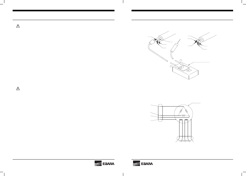
D C 500V M egger
G
L1
L3
L2
P ow er cable
P rotective device cable
P 3
P 4
P 2
P 1
G
+
_
Fig. 10
P1
P2
G
L3
L1
L2
Power cable
Motor
P3 P4 G
Protective device cable
Fig. 11