Dsc4, Instruction manual model – EBARA DSC4 User Manual
Page 6
06
INSTRUCTION MANUAL
Model
DSC4
3.3 Discharge Elbow Installation (Fig. 4)
WARNING: WHEN LIFTING THE PUMP, USE APPROPRIATE CRANE (OR HOIST) AND
LIFT SYSTEM.
CHECK POSITION AND TIGHTNESS OF LIFT SYSTEM SO THAT WEIGHT OF THE PUMP IS NOT
UNBALANCED.
FAILURE TO OBSERVE THIS PRECAUTION CAN RESULT IN SERIOUS ACCIDENTS.
Install the discharge elbow level on the bottom on the pump pit, and connect the guide pipe.
Support the guide pipe with bushings on discharge elbow and the guide pipe holder. If the guide
pipe requires a length exceeding 5.5 m, an extension or intermediate support may become
necessary, in which case we are available for consultation. When installing the discharge elbow,
the guide pipe must be vertical (with a tolerance of 1mm or less per 1m), using a plum bob. If it
is not vertical, it may become impossible to lift pump. Discharge elbow level should be with in
0.1 mm per 1 m, both in the “X” and “Y” directions shown in Fig. 4. It is recommended practice
that pipe installation be carried out with the discharge elbow covered to protect against entry of
concrete and mortar during the work.
CAUTION: FIX THE ARCHOR BOLTS TIGHTLY BY, FOR EXAMPLE, BY WELDING THEM
TO THE REINFORCEMENT BAR, ETC.
Y
X
Bushing
Fig 4
27
INSTRUCTION MANUAL
Model
DSC4
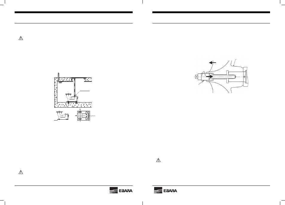
(2) Impeller disassembly
Remove the impeller bolt cap and impeller bolt with special tools.
Remove the impeller with Special pull out tool. (Refer to Fig. 23)
Fig. 23
(3) Mechanical seal replacement (Refer to Fig. 24)
(a) Remove the snap ring (A) from intermediate casing.
(b) Remove the mechanical seal by using push bolts (B).
For assembly, reverse the above steps.
After installing the mechanical seal, fi ll the threads (C) with the silicon-rubber sealant
(SHIN-ETSU CHEMICAL Co., Ltd. KE-45 or equivalent).
CAUTION: DO NOT COMPLETELY DISASSEMBLE THE MECHANICAL SEAL.
Special pull out tool
IMPELLER
(Left hand screw)