Dsc4, Instruction manual model – EBARA DSC4 User Manual
Page 16
16
INSTRUCTION MANUAL
Model
DSC4
Table 2 (Example)
(Source : Electrical Equipment Technical Standards, Ministry of International Trade
and Industry).
4.3 Protective Device Cable Connection (Fig. 15 and Table 3)
This pump have a leakage detector at the motor bottom and a thermal protector, in the stator coil
to protect the motor, with cable connections as illustrated in Fig. 15. Connect terminals P1 and
P2 for the thermal detector to P1 and P2 of the same control connector. Connect the remaining
terminal G to ground. Table 3 shows detailed specifi cations regarding protective devices.
Table 3
WARNING: AN EARTH LEAKAGE BREAKER MUST BE USED ACCORDING TO LAW TO
PREVENT ELECTRICAL ACCIDENTS.
Motor
classifi cation
Grounding
resistance
Grounding line
diameter
AC 600V below
10
Ω
φ1.6 mm
Thermal protector
Leakage detector
Type
9700K 06-215
OLV – 5 (fl oat type)
Manufacturer
SENSATA TECHNOLOGIES JAPAN
LTD.
NOHKEN INC.
Contact rating
AC 115V/230V×18A/12A (max)
AC 300V×0.5A (max)
Contact type
B-contact (normally closed)
B-contact (normally closed)
Cable terminal identifi cation
P1
P2
P3
P4
Material and size of cable
SOOW-A×#14
Fig. 15
For ground
G
For thermal
protector
P1
P2
For leakage detector
P4
P3
SOOW-A x #14x5 CORE
17
INSTRUCTION MANUAL
Model
DSC4
CAUTION: A MOTOR PROTECTIVE DEVICE SHOULD BE INSTALLED ON CONTROL
PANEL TO PROTECT THE SUBMERSIBLE MOTOR AGAINST OPEN-PHASE, OVER-CURRENT
OR INCHING.
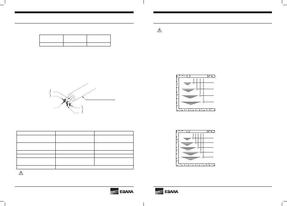
4.4 Water Level Switch Cable Connection (Fig. 16 and 17)
Figs. 16 and 17 illustrate typical fl oat switch applications for water level control.
Three (or four) fl oat switches are required for single unit operation, whereas four (or fi ve) are
necessary for two-unit alternating operation.
If you desire our Ebara Water Level Control Float Switch, ask us for a catalog.
Alarm (abnormal low level)
OFF
ON
Alarm (abnormal high level)
Fig. 16 Single Unit Operation
OFF
Alarm (abnormal high level)
ON (2nd Unit)
ON (1st Unit)
Alarm (abnormal low level)
Fig. 17 Two-Unit Alternating Operation