Dsc4, Instruction manual model – EBARA DSC4 User Manual
Page 14
14
INSTRUCTION MANUAL
Model
DSC4
3.8 Cable Installation (Fig. 13)
When the pump has been installed, pull out the power cable, protective device cable, water
level switch cable, etc. from the cable lead-out elbow on the fl oor and connect them to the
control panel.
CAUTION: HANDLE THE CABLES VERY CAREFULLY. IF THEY ARE BENT OR PULLED
EXCESSIVELY, THE CABLE AND THE MOLDED SEAL MAY BE DAMAGED, RESULTING IN
INSULATION FAILURE.
ALSO, CARE IS NEED TO PROTECT CABLE ENDS AGAINST WATER INTRUSION.
Note: The cables should be cut to the necessary length.
If the cable is too short, it can prevent lifting of the pump.
If the cable is too long and laid loose on the pump pit bottom, it could be sucked into the
pump.
If left coiled on the ground, it could be locally heated.
3.9 Floor Plate
Finally, install the fl oor plate over the pump pit, and the installation work is fi nished.
FLOOR PLATE
CABLE LEAD-OUT ELBOW
Fig. 13
19
INSTRUCTION MANUAL
Model
DSC4
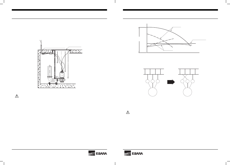
Fig. 18 Pump performance for Normal Rotation
Fig. 19 Change of Connections for Normal Pump Performance
WARNING:
CHOCK THE PUMP TO REDUCE THE TORQUE PRODUCED BY A LARGE
SIZED PUMP.
(2) If the pressure gauge or compound pressure gauge is not installed on discharge pipe.
If checks of the rotating direction of the pump in the water as described above cannot be
performed, proceed as follows.
Lay the pump on the ground. Turn switch on and off instantaneously, and check visually
the rotation direction through the discharge bore of the pump. The rotating direction of
the pump should be clockwise when viewed form above.
(Head)
Total head
(H1 + H2) m
Shaft output
(Amperage)
Total head
Rated output
(Rated amperage)
(Capacity)
Solid line : Normal
Broken line : Reversed
L1
L2
L3
3
L
1
L
2
L
Motor
Motor
L3
L1
L2
1
L
2
L
3
L