Dsc4, Instruction manual model – EBARA DSC4 User Manual
Page 5
28
INSTRUCTION MANUAL
Model
DSC4
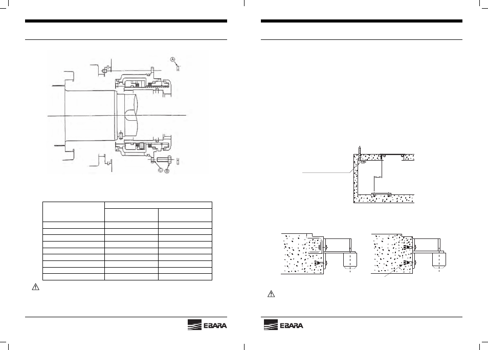
Fig. 24
(4) Torque table
Table 4
WARNING: WHEN MACHINES SURFACES ARE DAMAGED AND MUST BE REPAIRED, USE
AN APPROPRIATE GRINDER. DURING GRINDING WORK, APPROVED PROTECTIVE GOOGLES
MUST ALSO BE WORN.
Motor side
Impeller side
Bolt Size
Torque kg.m (Ft.lbs.)
Without anti seized
compound
With anti seized
compound
M8
1.1 (8)
0.8 (6)
M10
2.2 (16)
1.5 (11)
M12
3.8 (28)
2.6 (18)
M16
9.1 (66)
6.2 (45)
M20
17.8 (129)
12.1 (88)
M22
24.0 (174)
16.2 (117)
M24
30.8 (223)
20.9 (151)
M30
61.4 (444)
41.6 (301)
M36
107.0 (774)
72.4 (524)
05
INSTRUCTION MANUAL
Model
DSC4
3. Installation
3.1 Foundation
Place concrete to build up the fl oor and discharge elbow foundations to the values shown in
installation drawing. The discharge elbow foundation must have suffi cient size and strength to
support the weight of the pump body, submersible motor and accessories plugs the weights of
the discharge pipe, and to absorb vibrations and impacts resulting from operation. Usually, it
should weigh more than seven times the pump weight.
3.2 Floor Frame (Fig. 1, 2 and 3)
Install a cable lead-out elbow and a fl oor frame on the fl oor over the pump pit. Attach a guide
pipe holder securely to the fl oor frame with bolts. As the guide pipe must be installed vertically
(with a tolerance of 1mm or less per 1m), carefully check the positional relationship between
the fl oor frame location and the discharge elbow foundation. (See Fig. 1 * )
If the guide pipe holder is attached directly to the concrete, use hole-in anchor bolt as shown
in Fig. 3.
CAUTION: IF THE CABLE LEAD-OUT ELBOW IS TOO SMALL IN DIAMETER, THE CABLE
MAY BE HEATED WHERE IT RUNS THROUGH THE ELBOW.
*
Cable lead-out elbow
Fig. 1
Fig. 2 Fig. 3
Hole-in anchor bolt