Part 1 - quick start – Dynasonics D300_301 Series Doppler Ultrasonic Flow Meter User Manual
Page 4
Rev. 2/00 -1.3- 300/301
3. TRANSDUCER/POWER CONNECTIONS
A. Do not attempt to add additional cable to the
transducers.
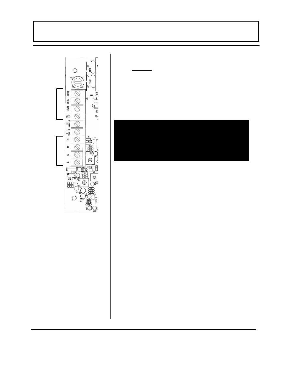
B. Refer to the WIRING DIAGRAM in Figure 1.2
for proper power and transducer connections.
Verify proper jumper selections are in place for
the power source. See Figures 2.2 and 2.3.
4. INITIAL SETTINGS AND POWER UP
A. Adjust the GAIN control [R10] to 1/4 turn from
full counter-clockwise rotation. Set the DAMP
control R110 to 1/2 turn from either stop.
B. Apply power to the instrument.
C. If the pipe is full of a flowing liquid, the LED
located on the bottom of the main circuit card
[D21] should begin flashing. If the LED does
not flash, gradually turn the GAIN control [R10]
clockwise until the LED just begins to flash
steadily. (Do not over adjust this setting as
ambient noise can influence readings.)
D. If possible, turn off the flow to the pipe. Verify
that the LED [D21] ceases to flash. If the LED
continues to flash when flow rate is zero, the
GAIN control [R10] is set too far clockwise and
ambient noise is influencing the readings.
Turn the control counter-clockwise until the
flashing ceases.
E. If the instrument passes steps 4C and 4D, the
basic setup of the instrument is complete.
PART 1 - QUICK START
IMPORTANT!
In order to successfully complete the configuration of
the D300/301 flow meter, the transducer must be
mounted on a pipe which is full of a flowing liquid. It
is normal to have zero readings and no signal indica-
tor LED with empty pipes or zero flow rate.
Figure 1.2
Power and Transducer
Connections
P
o
w
e
r C
onn
ec
ti
ons
T
rans
duc
er
C
onn
ec
ti
ons