Part 3 - transmitter installation – Dynasonics D300_301 Series Doppler Ultrasonic Flow Meter User Manual
Page 16
Rev. 2/00 -3.2- 300/301
used for line power; the right conduit hole for
transducer connections.
5. If additional holes are required, (analog outputs,
etc.) drill the appropriate size hole in the
enclosure’s bottom. Use extreme care not to run
the drill bit into the wiring or circuits cards.
Electrical Connections
1. To access terminal strips for electronic
connections, loosen the two screws in the
enclosure door and open the door.
2. Guide the transducer terminations through the
transmitter conduit hole located on the right side
of the enclosure. Secure the transducer cable
with the supplied conduit nut.
3. The terminals on the transducer cable are coded
PART 3 - TRANSMITTER INSTALLATION
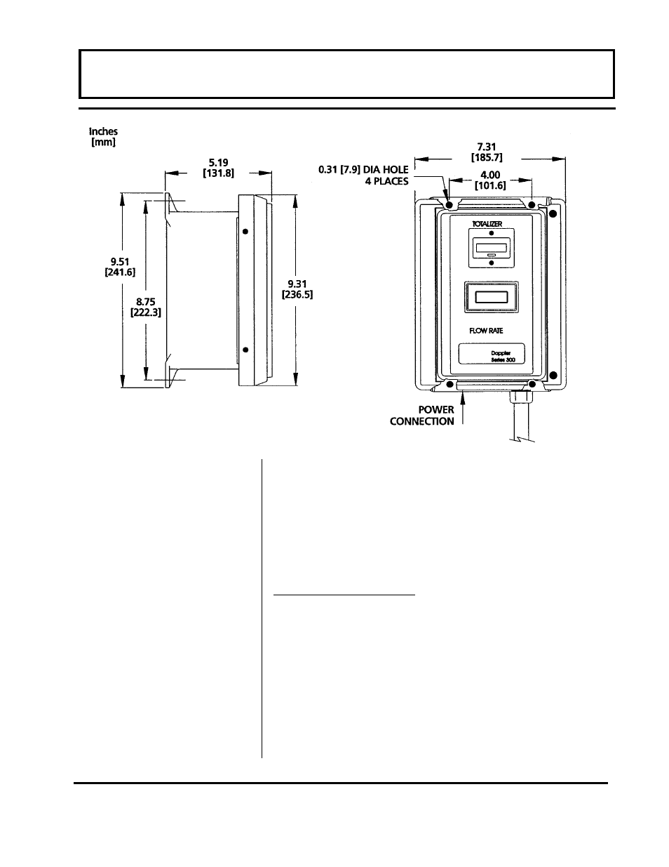
Figure 3.1