AMD Am79C930 User Manual
Page 55
P R E L I M I N A R Y
AMD
55
Am79C930
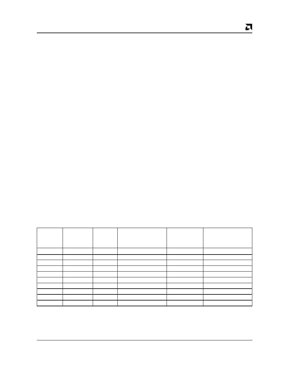
Diversity decision logic for determining if a satisfactory
antenna has been found. These inputs to the Stop Di-
versity decision logic are enabled by specific bits of
TCR28. The UBDSD bit of TCR28 is used to select/
deselect the Baud Determination of Stop Diversity for
use in Stop Diversity decisions and the URSSI bit of
TCR28 is used to select/deselect RSSI information in
Stop Diversity decisions. Note that the URSSI bit of
TCR28 is also used to select/deselect RSSI information
for use in CCA decisions.
The possible Stop Diversity results are shown in the
table below.
The current stop diversity result is reported in the
ANTLOK bit of TIR26.
A rising edge of ANTLOK will set the ALOKI (Antenna
Lock Interrupt = Diversity switching stopped) bit of TIR5.
This bit may serve as an interrupt to the 80188 core, or
the interrupt due to this bit may be masked and the bit
can be polled by the 80188 core.
The antenna diversity switching is signaled with the
ANTSW bit of TIR4. This bit reports a change in the an-
tenna selection. This bit may serve as an interrupt to the
80188 core, or the interrupt due to this bit may be
masked and the bit polled by the 80188 core.
The current antenna selection may be read from the
ANTSLT bit of TIR26.
The current RSSI limit comparison test result may be
read from the RSALT bit (RSSI Above Limit) of TIR28.
Automatic Antenna Diversity switching may be disabled
through appropriate setting of the ANTSEN bit of TIR26.
Manual setting of the antenna selection is then allowed
through the ANTS bit of TIR26.
TXC As Input
For typical transceiver connections, the signal TXC is
defined as an input to the transceiver. However, for
some transceiver connections, the signal TXC is de-
fined as a
transceiver output. The Am79C930 device
can accommodate both types of transceivers by allow-
ing the TXC pin to be defined as either output or input.
In the case where the TXC pin is as output from a trans-
ceiver, the TXCIN bit of TCR30 must be set to a 1 in
order to change the direction of the TXC signal. When
this is done, a 16-bit serial-FIFO is added into the path of
the TX data in order to accommodate a small amount of
possible mismatch between the transceiver’s TXC fre-
quency and the Am79C930 device’s internal TXC fre-
quency. When this FIFO is inserted into the transmit
data stream, an additional delay of 8-bit times is incurred
between the assertion of the TXS bit of TIR8 and the as-
sertion of the first transceiver transmit control signal in
the transmit control sequence.
If the mismatch between the transceiver’s TXC fre-
quency and the Am79C930 device’s TXC frequency is
too large, then a serial-FIFO overflow or underflow con-
dition may occur. When this situation arises, an error will
be indicated by the ATFO or ATFU bits of TCR11.
IEEE 1149.1 Test Access Port Interface
An IEEE 1149.1 compatible boundary scan Test Access
Port (TAP) is provided for board level continuity test and
diagnostics. All digital input, output, and input/output
pins are tested. ADREF,
TRST
, TCK, TMS, TDI, TDO,
and PMX2 pins are not included in the boundary
scan test.
Stop Diversity
Baud Detect Stop
Result
UBDSD
URSSI
STPEN
Stop Diversity
RSSI >= RSSI
(ANTLOK Bit
TCR28[2]
TCR28[0]
TCR28[3]
Decision
Lower Limit
of TIR26)
X
X
0
don’t care
don’t care
ANTLOK = FALSE
0
0
1
don’t care
don’t care
ANTLOK = TRUE
0
1
1
don’t care
yes
ANTLOK = TRUE
0
1
1
don’t care
no
ANTLOK = FALSE
1
0
1
TRUE
don’t care
ANTLOK = TRUE
1
0
1
FALSE
don’t care
ANTLOK = FALSE
1
1
1
TRUE
yes
ANTLOK = TRUE
1
1
1
TRUE
no
ANTLOK = FALSE
1
1
1
FALSE
yes
ANTLOK = FALSE
1
1
1
FALSE
no
ANTLOK = FALSE