Block diagram bus interface unit – AMD Am79C930 User Manual
Page 4
4 Am79C930
P R E L I M I N A R Y
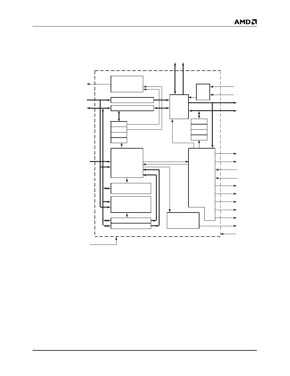
BLOCK DIAGRAM
Bus Interface Unit
A14–0 or
LA23–17, SA16–0
D7–0
CLKIN
Slave
Control
PCMCIA
and ISA
Memory
and I/O
Address Buffer
Data Buffer
SIR0
System
Interrupt
Generator
SIR1
...
SIR7
ISA Memory Base
ISA I/O Base
MD[7:0] MA[16:0]
80188
Interrupt
Generator
IREQ
PCMCIA
Config Registers
ALE
CA16
Latch
Bus
Multi-
plexer
CAD7–0
CA15–8
MIR0
MIR1
...
MIR15
MOE
MWE
UCS
LCS
SRDY
XCE
FCE
TAICE
SCE
INT1
RESET
PCMCIA
or
ISA Control Signals
Plug and Play
Control Module
Slave
Control
and
Arbitration
for
Memory
Interface
Bus
20183B-2
See also other documents in the category AMD Hardware:
- Radeon 4850 (18 pages)
- Phenom AM2r2 (6 pages)
- GA-K8N51GMF-9 (80 pages)
- Socket AM2+ Quad Core Processor SB750 (63 pages)
- Turion 64 X2 (2 pages)
- GA-M61PM-S2 (80 pages)
- Socket AM2+ Quad Core AMD Processor 790GX (53 pages)
- 7ZMMC (36 pages)
- Geode SC1200 (443 pages)
- CS5535 (36 pages)
- Geode LX800 (46 pages)
- ATI RADEON HD 2600 (62 pages)
- LE-363 (45 pages)
- SimNow Simulator 4.4.4 (269 pages)
- GA-MA69VM-S2 (88 pages)
- KM780V (21 pages)
- SBX-5363 (55 pages)
- AM79C971 (1 page)
- K3780E-S (43 pages)
- GEODE LE-366 (45 pages)
- 7ZX-1 (46 pages)
- Geode SC2200 (429 pages)
- Phenom II (6 pages)
- ATI Radeon x1700 FSC (22 pages)
- Turion 64 (3 pages)
- 1207 (62 pages)
- CrossFire 550X (16 pages)
- Athlon 27488 (104 pages)
- Geode LX [email protected] (680 pages)
- GA-M61SME-S2 (80 pages)
- N2PA-LITE (45 pages)
- GA-K8NSC-939 (80 pages)
- GEODE NX800LX (27 pages)
- LV-651 (50 pages)
- Athlon 6 (19 pages)
- Geode SC3200 (428 pages)
- SEMPRON 10 (102 pages)
- GA-K8N ULTRA-9 (80 pages)
- Geode LX CS5536 (8 pages)
- MINI-ITX LV-651 (50 pages)
- GA-K8N51GMF-RH (88 pages)
- ATI RADEON HD 2400 (64 pages)
- GA-M55S-S3 (88 pages)
- GA-M51GM-S2G (88 pages)